ELECRAFT K4 OPERATING MANUAL
Rev C22, September 18, 2022
USING THE BUILT-IN OPERATING MANUAL
USING TAP, HOLD, and TOUCH CONTROLS
INTERNAL & EXTERNAL TRANSVERTERS
_________________________________________________
This operating manual is a compact reference to all K4 controls, connectors, display elements, and menu entries. It also provides context-sensitive help during operation.
Please read the fully illustrated short-form manual, Introduction to the Elecraft K4, to become familiar with control and connector locations.
To view the built-in operating manual, tap the button labeled "?" at the lower left-hand corner of the LCD screen:
For help with the most recent controls used, tap the LAST CTRL button one or more times.
To scroll through text, rotate the VFO A knob. Navigate by clicking on underlined links and using the forward/backwards buttons. Tap the table of contents button to return to the top.
To search by topic, tap the magnifying glass button. If there's more than one match, the up/down arrow buttons will navigate among them. Tap the magnifying glass button again to exit match navigation and return to scrolling.
For a full-screen version of the operating manual, tap the resize button.
Important cautions are shown in red.
The following text conventions are used when referring to controls:
[Physical Switch] <Touch Control> {Knob}
Switch, touch, and knob controls are shown in white for tap, yellow for hold, as on the transceiver itself.
Many LCD labels, icons and graphics also function as touch controls. Those which appear in the form of labeled switches are referred to as 'buttons' to differentiate them from physical switches.
MENU ENTRIES are shown as MENU:Name, e.g. MENU:LCD Brightness. For a full list of menu entries, see IV. MENU LISTING.
** Indicates a feature that is still in development.
The K4 is a high-performance, direct-sampling software-defined radio (SDR). It covers the 160 ~ 6 m bands, with continuous receive from 100 kHz ~ 54 MHz. 10 W and 100 W models are available. It can be used with internal or external transverters to cover bands from VHF up.
Among the K4's notable features: A large color touch screen, as well as support for an external monitor; extensive, easy to use controls; rich analog and digital connectivity; dual receive; built-in data modes, and wide range antenna tuner. In addition to its extensive front panel controls, the K4 has full mouse support, and can also be controlled by an Elecraft K-Pod.
The K4's compact size and weight, combined with 11-15 VDC operation and low current drain, make it suitable for field, travel, or home station use.
Since the K4 is an SDR, Elecraft can provide updates to its signal processing algorithms with software changes rather than by adding new hardware. This ensures that the K4 can take advantage of new modes, bands, or other features in the future. For example, a recent addition was advanced speech compression and CESSB (Controlled Envelope Single Sideband), a DSP feature that boosts average talk power by as much as 8 dB.
The K4 uses direct sampling, meaning that signals are digitized right at the receiver inputs, and the transmitter's amplifier chain is also driven by a digitized signal. Older SDR architectures digitized signals at a low intermediate frequency (IF), resulting in poor suppressions of down-conversion or up-conversion images.
There are three models: the basic K4, with one set of receive filters and one analog-to-digital converter (ADC); the K4D, with a second set of receive filters and a second ADC; and the K4HD, which adds a superheterodyne front end that can be enabled as needed to provide even greater dynamic range. The superhet module uses high-performance, narrow-band crystal filters such as those used in the Elecraft K3S.
Even the basic K4 provides simultaneous dual receive on the same or different bands/modes. However, the K4D and K4HD models include an additional receiver module (KRX4) with a second set of band-pass filters, improving signal handling during dual-receive operation on different bands. The second receiver also permits diversity reception, i.e., the use of different antennas for the two receivers to counteract fading (QSB).
A basic K4 can be upgraded to a K4D by installing the KRX4 option. Similarly, a K4D can be upgraded to a K4HD by installing a KHDR4 module. Other internal options and external accessories are applicable to all three models, including a wide-range ATU (KAT4), MH4 microphone, SP4 external speaker (1 or 2). For further information, visit www.elecraft.com.
CAUTION: Ground your K4 properly before operation using the provided wing nut ("GND"). For suggestions, see www.arrl.org/grounding.
Even though the K4 has extensive internal protective circuitry, external protection against lightning strikes is strongly recommended, especially in lightning-prone areas.
During storms and when the station is not in use for an extended period, disconnect ALL equipment from the K4, including antennas, power supply, routers or hubs, and computers. Ethernet, USB, and RS232 cables are a frequent source of damaging surge voltages.
Provide at least 1" of free space both above and behind the transceiver. Ventilation holes on the bottom and left sides must also not be blocked.
If the K4 is placed on a desk or table, deployment of the tilt stand is strongly recommended to facilitate easier interaction with the touch screen. This will also improve display viewing angle.
Carefully peel the protective film off the LCD. There's a small plastic tab at the upper right corner for this purpose. If the film is left on, it will degrade the appearance of LCD graphics as well as touch screen performance.
Use the shortest practical length of power cable, with heavy wire gauge to minimize voltage drop. The supplied power cable includes fuses in both legs. The supplied cable is #12 AWG, and the fuses in each leg are rated at 25 amps.
A power supply voltage of 13.8 to 14.2 V is preferred. For 100 W use, a 30 amp supply is recommended. For 10 W use, a 5 amp supply will suffice. NOTE: If use of a switching supply results in low-pitched repetitive noise or other artifacts when monitoring your K4's signal in another receiver, consider using a well-regulated and filtered linear supply.
Minimum supply voltage is 11.0 V. The K4 will automatically reduce power output if the supply voltage is too low to maintain good IMD performance at the selected RF output level.
Refer to the REAR PANEL CONNECTIONS section, below, for descriptions of all connectors and interfacing requirements. At minimum you'll need to connect a power supply, antenna, and station ground.
Once your K4 is installed and you're ready to operate, you can get started in one of two ways: (1) read the FRONT PANEL REFERENCE section to learn about each of the controls, or (2) jump to the OPERATING INSTRUCTIONS section, which is more procedural in nature.
An internet connection is the preferred way to do software updates. To initiate an update, tap primary function button <Fn>, then hold <UPDATE>. Once the software update screen is displayed, tap the <?> button for detailed instructions on how to update software and read release notes.
Rear panel connections are briefly described below, from left to right and top to bottom as viewed from the back. The information provided in this operating manual is limited; refer to Introduction to the Elecraft K4 for more details.
These are the HF/6 m transmit-receive antenna jacks. If an ATU is not installed, only the ANT 1 jack will be present. Also see ANTENNA SELECTION.
Antenna jack for use with an internal transverter, if applicable. If no transverter is installed, the jack will not be present.
Anderson Power Pole (APP) connectors for 11-15 V DC supply. 30 amp supply recommended for 100 W use. See INSTALLATION INSTRUCTIONS for cable and fusing requirements.
12 V switched output for use with accessories, 1.5 amps max (protected by self-resetting fuse).
For attachment of station ground. See INSTALLATION INSTRUCTIONS.
If transmit IMD optimization** is enabled for use with an external linear amplifier (such as the Elecraft KPA1500), connect its transmit output sample port to TX SMPL IN. Signal level and calibration details to be determined.
Transmit IMD optimization can also be enabled for use with the K4's internal amplifier stages.
This jack can be used as a general-purpose receive antenna, or for connection to an external transverter (in conjunction with XVTR IF OUT). See TX AND RX ANTENNA SELECTION.
This can be used as the output drive signal for an external transverter.
General-purpose receive antenna input. See ANTENNA SELECTION.
When the RX ANT OUT jack is active, its signal can be used along with RX ANT 1 IN or XVTR IF IN/RX ANT 2 IN to provide a path through an external band-pass filter, splitter, etc. The RX ANT OUT signal is obtained from the transmit antenna path, so it passes through the ATU (if applicable) as well as the transmit low-pass filters and T/R switch.
RX ANT OUT is only active if the main and sub receivers are both configured to use receive-only antennas. See Using RX ANT OUT.
Connect to station router or modem. Compatible with 10/100/1000 megabit rates. A high quality shielded cable is strongly recommended; refer to Elecraft web site for available cable(s).
Ethernet connectivity is preferred for software updates and remote control applications, such as our Virtual K4 program (see REMOTE CONTROL).
Note: If you have any difficulty with software updates, tap the "?" button from within the UPDATE function. Also see TROUBLESHOOTING.
The rear panel has two type A USB jacks and one of type B, labeled "PC". There is an additional type A jack on the front panel. Any of the type A jacks may be used with a keyboard, mouse, memory device, or Elecraft K-Pod. Wireless adapters may be used. Each rear USB-A jack can provide up to 400 mA max to peripheral devices.
The type B USB jack provides two virtual COM ports, referred to in this manual as USB-PC1 and USB-PC2, that can be used for radio control and soundcard I/O (digital version of LINE IN / LINE OUT). LINE OUT is stereo; LINE IN is mono. Connect the cable to any USB-A jack on a host computer or hub.
To set the baud rates for these ports, use the Serial USB-PCn: Baud Rate menu entries. Refer to software application manuals for port setup instructions. (Plugging in new devices, including the K4, may alter COM port assignments.)
To use the RTS and DTR signals of the USB-PCn ports for transmit functions (PTT, KEY, or FSK select), or to configure them for Auto-Info frequency data output (AI), use the associated Serial USB-PCn menu entries.
To set up these ports for soundcard receive audio, first tap the <MAIN RX> function button, then tap <LINE OUT>. For soundcard transmit audio setup, tap <TX>, then <LINE IN>. Also see TX button description.
A third COM port is also available for remote control/data; see RS-232, below.
Connection for an external monitor. The monitor can be configured to show only the panadapter, which may be configured differently from the panadapter shown on the LCD. See Ext. Monitor Function and LCD SCREEN AND TOUCH CONTROLS.
A 10 MHz reference signal may be connected to this jack. The K4's internal reference oscillator will lock to this signal when present. Also see ER100 (Error Messages).
This is an analog audio input (nominally 600 ohms) for connection to computers or other station equipment that supply transmit audio to the K4. An example of this is a software application that supplies data-mode audio signals, e.g. FT8, RTTY, or PSK31. In voice modes, LINE IN can be used in lieu of, or in conjunction with, microphone audio; see TX button description.
Most computer software can alternatively provide LINE IN signals from a virtual COM port, eliminating the need for analog cabling and potentially reducing noise. See description of rear-panel USB connector, above.
This is an analog audio output (stereo; nominally 600 ohms) for connection to computers or other station equipment that obtain receive audio from the K4. An example of this is a software application that demodulates data-mode audio signals such as FT8, RTTY, or PSK31, as well as CW signals.
Receive audio is always present at both the analog LINE OUT jack and the soundcard output (see USB). If the sub receiver is turned on, the right channel supplies sub-RX audio. If the sub RX is turned off, then right-channel audio is identical to left (main RX). Also see MAIN RX button description.
Most computer software can alternatively accept LINE OUT signals from a virtual com port, eliminating the need for analog cabling and reducing noise. See description of rear-panel USB connector, above.
Note: Windows Sound Control Panel does not accurately show sound input level. The correct levels are shown by WSJT, MMTTY, and other apps.
Left and/or right speaker audio (nominally 4 to 16 ohms). 1 or 2 non-powered speakers such as the Elecraft SP3 or SP4 may be connected to this jack. Powered speakers may also be used, though attenuation may be needed between the speaker jack and the external speakers to prevent overdrive.
Plugging in external speaker(s) disconnects the internal speaker.
CAUTION: To avoid possible damage to the second speaker channel, always use a stereo plug, even when connecting only a single speaker.
If only one external speaker is connected, use the left channel output (tip), and set MENU:Speakers to 1. As with the internal speaker, a single external speaker will mix main and sub receiver audio.
If two speakers are connected, set MENU:Speakers to 2. Audio is then routed as follows:
• If the sub RX is turned ON, the left speaker output supplies main-RX audio, and the right speaker output supplies sub-RX audio. For balance control, see RF Gain, Squelch, and Main/Sub Balance. For main/sub RX audio mix controls, see the RX Audio Mix with Sub ON menu entry.
• If the sub RX is turned OFF, the speaker outputs are identical, unless stereo effects are in use or left/right balance is changed. Also see AUDIO EFFECTS (AFX).
Connection for rear-panel headphones, in parallel with the front-panel headphones. Requires a 1/8" (3.5 mm) plug, either mono or stereo. Plugging in headphones disconnects the speaker(s) unless the Speakers + Phones menu entry is set to Yes.
Connection for rear-panel microphone. Bias and gain for the rear-panel mic can be set up independently from the front panel mic. Tap <TX> primary function button, then the <MIC INP> and <MIC CFG> secondary function buttons.
This DE9 connector provides a true-RS232 COM port that can be used for remote control of the K4. The K4 can also emit Auto-Info (AI) frequency data on this port for use with external devices such as antenna controllers.
To configure the data rate for this port, set up transmit functions for the RTS and DTR lines (PTT or KEY), or configure it for auto-info (AI), use the corresponding Serial RS232 menu entries.
RCA jack for use with external PTT controls, e.g. a foot switch or station controller. Pull this input to ground (0V) to key the transmitter.
Additional PTT sources can be defined using MENU: Serial IO functions for USB-PC1, USB-PC2, and RS232. The DTR and/or RTS signals from any of these ports can be used in any combination.
RCA jack that provides a keying output signal for use in keying amplifiers or other station gear. The signal goes low (0V) when the K4 is keyed by any method.
To configure this output to match the requirements of external equipment, use menu entry TX DLY, KEY Out to RF Out.
Note: If you're controlling an Elecraft KPA500 or KPA1500 amplifier from the K4 via the 15-pin accessory cable, you normally won't need to use a separate KEY OUT cable. There are exceptions to this; refer to the key line interrupter information in your amplifier manual.
1/4" (6.35 mm) keyer paddle input jack. The dot and dash inputs on this jack activate the K4's built-in CW keyer.
To set up Iambic keying mode, reverse the dot/dash paddles, or adjust keying weight, tap the <TX> function button, followed by the <PDL>, <IAMB>, or <WEIGHT> buttons. Applicable modes include CW, FSK, and PSK.
1/4" (6.35 mm) keying input jack for use with a hand key, bug, electronic keyer, or other keying device.
Additional KEY input sources can be defined using MENU: Serial IO functions for USB-PC1, USB-PC2, and RS232. The DTR and/or RTS signals from any of these ports can be used in any combination.
Accessory IO connector (DE15). This connector provides a number of input signals for use in controlling the K4, as well as outputs for controlling amplifiers, antenna switches, and other external equipment. The list below summarizes these functions; refer to the Introduction to the Elecraft K4 manual for further details.
Pin Description
1 FSK IN (active low); can be used in FSK mode (also see RS232 and USB ports)
2 AUXBUS in/out; controls Elecraft amps, transverters, and the KRC2
3 BAND1 OUT; BAND0-BAND3 outputs provide 4-bit parallel band indication
4 PTT IN (in parallel with PTT jack as well as mic PTT)
5 Ground
6 DIGOUT0; low-power external transverter select
7 K4 "power on" signal or TX Inhibit input (see TX Inhibit Mode)
8 Power On; pull to ground (0 V) for 0.2 to 1.0 sec to turn K4 on, then release
9 BAND2 OUT; BAND0-BAND3 outputs provide 4-bit parallel band indication
10 KEY OUT LP; low-power keying output (10 mA max) (see note below)
11 DIGOUT1; per-band/per-antenna output (see DIGOUT1 menu entry)
12 Ground
13 BAND0 OUT; BAND0-BAND3 outputs provide 4-bit parallel band indication
14 BAND3 OUT; BAND0-BAND3 outputs provide 4-bit parallel band indication
15 EXT ALC; negative-going ALC voltage from external amplifier
Note: If you're controlling an Elecraft KPA500 or KPA1500 amplifier from the K4 via the accessory cable, you normally won't need to use a separate KEY OUT cable. There are exceptions to this; refer to the key line interrupter information in your amplifier manual.
_________________________________________________
This section lists and describes all of the K4's controls and display elements, generally proceeding from left to right on the front panel.
** Indicates a feature that is still in development.
The following text conventions are used when referring to controls:
[Physical Switch] <Touch Control> {Knob}
All physical and touch controls are described in the FRONT PANEL OVERVIEW section, which follows.
Each of the K4's physical switches has both a tap function (white label) and a hold function (yellow label). A tap is a brief press, while a hold is any press longer than about 1/2 second. For example, [RATE] is a tap function, while [KHZ] is a hold function of the same physical switch.
The K4's touch screen provides quick, convenient access to the rig's most-used features. Many of the icons and labels are also touch controls.
Examples:
• You can touch VFO digits to select a tuning rate as an alternative to using the [RATE] and [KHZ] switches.
• To bring up the mode-select button group, tap the mode identifiers near each VFO display, or tap the [MODE] physical switch above the VFO A knob.
• To select a receive antenna, tap the antenna name icons for each receiver or use [RX ANT] and [SUB ANT].
On-screen buttons can have one or two functions. For example, the <LAST CTRL> button in the operating manual screen has only a white label so it can only be tapped. A yellow label on a button indicates that a hold function is also available.
The three multi-function knobs to the left of the LCD also have built-in pushbutton switches, giving them tap and hold functions. Tap a knob to select a function to adjust; hold to select an additional function labeled in yellow below the knob.
Each of the specially shaped LCD buttons associated with the multifunction knobs shows a primary function (upper label), and a secondary function in yellow italics, accessed by tapping the button a second time. A knob always controls the parameter associated with the upper label on the selected button.
A large (7" diagonal) color LCD forms the heart of the K4's user interface. Most of the screen is dedicated to either a single panadapter (associated with VFO A or VFO B), or split between dual panadapters (centered below the VFO A and VFO B displays, respectively). Between the VFOs and panadapters are the bar graph meters and icons for transmit and receive. Along the bottom edge of the LCD are the Info button (<?>) and seven primary function buttons (see PRIMARY FUNCTIONS.)
Some LCD elements are color-coded, as follows: orange = TX, blue = main RX, green = sub RX. (Alternate color schemes may be provided in the future.)
The remaining controls are physical knobs and switches, arranged similarly to that of the Elecraft K3/K3S transceiver:
• FAR LEFT SIDE: Transmit and antenna-selection controls.
• TO THE LEFT OF THE LCD: Three multi-function knobs, each with two associated touch buttons. These provide quick access to parametric settings for the current operating mode. Below the multi-function knobs is a concentric knob controlling main/sub receiver AF gain.
• LCD AND TOUCH CONTROLS: See LCD SCREEN AND TOUCH CONTROLS.
• TO THE RIGHT OF THE LCD: VFO A knob, LED status indicators, and numeric keypad. Keypad switches each have tap and hold functions. They are organized in three rows: message play (top), receive functions (middle), and VFO controls (bottom). Surrounding the VFO A knob are four additional VFO controls including the SUB/DIVERSITY switch.
• FAR RIGHT SIDE: Memory STORE/RCL switches, VFO B knob, and RIT/XIT offset controls. The latter double as programmable functions PF1-PF4.
There are three connectors on the front panel:
The front mic jack is an Elecraft standard 8-pin type. It is compatible with the Elecraft MH4 and other K3/K3S-compatible microphones. Bias, gain, and mic PTT/UP/DOWN controls are configured using <TX> <MIC INP> and <MIC CFG>. For pin connections, refer to Introduction to the Elecraft K4.
MH4 Settings (recommended): Preamp=off, Bias=on, Buttons=PTT/UP/DN.
1/4" (6.53 mm) front phones jack. Can be used with mono or stereo plugs. Plugging in headphones disconnects the speaker(s) unless the Speakers + Phones menu entry is set to Yes. It may take up to 3 seconds to for front headphone plug insertion or removal to be detected.
NOTE: Some headphones (e.g. Bose QC35) or other audio devices have a capacitor in series with their plug. These will not work with the front phones jack unless a resistor (typically 15-51 ohms) is added in parallel. The front phones jack depends on the transducer providing a resistance path to ground when inserted.
This is a USB type A jack. Like the two type A jacks on the rear panel, it may be used with a keyboard, wireless keyboard, USB flash memory device, Elecraft K-Pod, mouse, or mouse transceiver module. The front USB jack can provide up to 900 mA max to peripheral devices (400 mA recommended).
The group of switches to the left of the LCD includes transmit and antenna functions and the power on/off switch.
Tap [POWER] to turn the K4's power on or off.
NOTE: Always turn the K4 off using its power switch. If you need to turn off the power supply as well, wait until the K4 has completely powered down. (This may take several seconds. You'll hear a number of relays turning off.)
Tap [TUNE] to enter tune mode at the power level set by the {XMTR} <PWR> knob function. This puts out a CW signal in any operating mode.
By default the same power output level is used on all bands. To save power level per-band, set MENU:Per Band Power to On. With this setting, a separate power output level for each band is also maintained for use with Elecraft KPA-series amplifiers.
Holding [TUNE LP] uses the power level specified by MENU:TUNE LP (Low power TUNE). This is intended for use with external amplifiers and antenna tuners that have specific drive power requirements.
Tap [XMIT] to place the K4 in transmit mode. This is the equivalent of holding a mic PTT button or asserting any of the other PTT lines (e.g., at the PTT IN jack). Tap [XMIT] a second time to exit transmit mode.
In CW, FSK, and PSK modes, tapping [XMIT] "pre-arms" the transmitter for transmit, switching all downstream gear connected to KEY OUT. However, no signal will be transmitted until the radio is keyed by some method. Direct keying methods include a hand key or external keyer, keyer paddle, attached keyboard, or the M1..M4 message buttons. A computer can key the transmitter via the RTS and DTR pins on the three serial ports, as well as by using remote-control commands (e.g., "TX;").
Also see VOX, which can be used for keying in all modes.
Hold [TEST] to enter TX test mode. In this mode, you can still key the transmitter (and any gear keyed by the KEY OUT jack), but power output will be zero.
The primary uses of [TEST] are:
• to pre-adjust mic or LINE IN gain prior to transmitting a signal (see {XMTR} knob functions <MIC> and <CMP>)
• to practice sending CW off-air
• to test T/R switching of downstream equipment
If a KAT4 ATU is installed, tapping [ATU TUNE] will initiate antenna matching, using a power level of 5 to 10 watts. This will cause the relays on the ATU to cycle for typically 1 to 4 seconds. Matching terminates automatically, and the resulting LC network settings are saved per-band, per-antenna. Up to 32 LC data values are stored for each band/antenna combination, allowing the K4 to "learn" the right matches for your antenna system in the course of normal operation.
Usually a match will be found with an SWR of < 2.0:1. If not, try tapping [ATU TUNE] a second time within 5 seconds; this causes the ATU to try more relay combinations, useful for narrow-banded antennas. Extended matching can take up to 10 seconds. However, once all antennas have been matched at multiple points on each band, retuning will rarely be needed even for antennas that are narrowband.
Each time you transmit, the K4 makes sure that the stored LC settings closest to your operating frequency are used. For this reason, after you move the VFO and transmit, you may hear relays switching briefly (~10 ms).
Note: Any HF frequency that appears outside of the ATU's segment map can still use the ATU for matching purposes, but only one LC setting is saved per-band/per-antenna for this purpose. (Details on ATU band/frequency bins TBD. Most MARS frequencies fall within the ham-band segment map.)
For info on ATU antennas, see ANTENNA SELECTION.
Holding [ATU] alternates between ATU in and bypassed, as indicated by the orange ATU icon near the upper middle of the screen (TX icon area).
In speech or audio data modes, the [VOX] switch enables or disables voice-activated (or audio-activated) transmit. VOX sensitivity and anti-vox controls can be accessed by tapping <TX>, then <VOX GAIN> or <ANTIVOX>.
In CW, FSK, and PSK modes, turning VOX on allows "hit-the-key" transmit, eliminating the need to first tap XMIT or activate PTT. This is the default. When VOX is enabled you can also transmit immediately by tapping message play buttons [M1]-[M4], or, if text decode is turned on, by entering text using a keyboard.
When VOX is on, an associated orange icon appears in the TX icon area.
Hold [QSK] to turn QSK CW (and the associated orange icon) on/off.
"QSK" means "break-in keying." This is a type of CW operation where the operator can hear received signals between letters or even between dots and dashes. This in turn allows other stations to "break in" simply by transmitting. QSK is especially useful in contesting, DXing, and high-speed CW QSOs.
The K4 actually allows received signals to be heard in this way even with QSK turned off, as long as the radio is in [VOX] mode and the {XMTR} <DLY> value is set to a small value (default is 0.00 seconds). However, turning QSK on further optimizes CW T/R switching to allow the receiver to recover more quickly. This can easily be observed by setting {XMTR} <WPM> to 20 WPM or higher and sending a string of dots. (Please use TX TEST mode for this purpose so a signal is not actually transmitted.) Turning QSK on automatically uses the equivalent of DLY = 0.00, regardless of the user's DLY setting.
Some operators prefer to leave QSK off to reduce the fatigue of listening to receive audio between CW elements. To further delay receive recovery, use larger values of {XMTR} <DLY>. This is useful with slower code speeds.
Tapping [ANT] cycles through the available transmit antennas, as indicated by the orange ANT1-2-3 icon in the TX icon area of the display. Also see ANTENNA SELECTION.
[REM ANT] will be used in a future software release to provide convenient access to remote antenna switches, rotator controllers, or related equipment.
Tap [RX ANT] to select one of the available antennas for use with the main receiver. See ANTENNA SELECTION.
Hold [SUB ANT] to select one of the available antennas for use with the sub receiver. See ANTENNA SELECTION.
The K4 has three multi-function controls, each handling a group of related functions: XMTR, FILTER, and RF/SQL. The knobs incorporate push-button switches which are tapped or held to select among parameters to adjust.
Each knob is accompanied by two buttons on the LCD. These buttons each have two labels, one of which is currently available for adjustment. The button in each pair that is selected is highlighted by a colored rectangular indicator: orange for XMTR, blue or green for FILTER, blue or green for RF/SQL. (Blue pertains to VFO A/main RX and green to VFO B/sub RX).
Below the three multi-function controls is a concentric knob that controls main or sub AF gain.
These four controls are further described in the sections that follow.
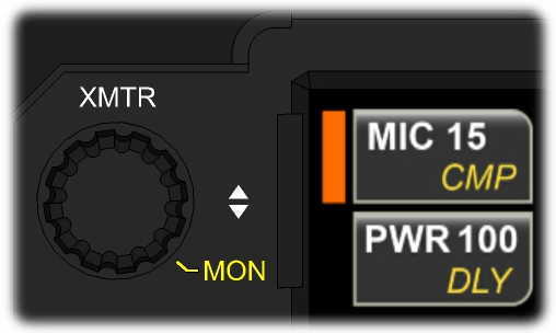
Rotate {XMTR} to adjust often-used transmit functions.
In all operating modes, tapping the lower LCD button adjacent to this knob selects <PWR> output or VOX <DLY> for adjustment. Tapping the upper LCD button selects either <MIC> and <CMP> (in speech modes) or <WPM> and <PITCH> (in CW, FSK, and PSK modes, which can all be used with a CW keyer paddle). Tap a button a second time to alternate between its two functions.
{XMTR} <PWR> normally sets the power in watts. If MENU:XVTR Out Test is in effect, or an external transverter band is in use, the value will be in milliwatts (mW).
Tapping the {XMTR} knob is an alternate way to change the LCD button selection. Holding the knob allows adjustment of [MON] (speech or sidetone monitor level). LINE OUT level for transmit monitoring is set independently using MENU:TX Monitor Level, Line Out.
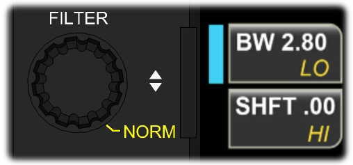
Rotate {FILTER} to adjust receiver filter bandwidth and shift, or hi-cut and lo-cut.
If the button selector color is blue, the main receiver's passband will be adjusted. If the selector is green, the sub receiver's passband will be adjusted. To select the sub RX for passband adjustment, either tap [B SET] (near the VFO B knob) or tap the <SUB RX> primary function button. Both illuminate the B SET icon.
Tapping the {FILTER} knob's lower LCD button selects either <SHFT> or <LO-CUT>, while the upper button selects <BW> (bandwidth) or <HI-CUT>. Tap a button a second time to alternate between its two functions.
Tapping the {FILTER} knob changes the LCD button selection. Holding the knob selects [NORM], a per-mode nominal passband.
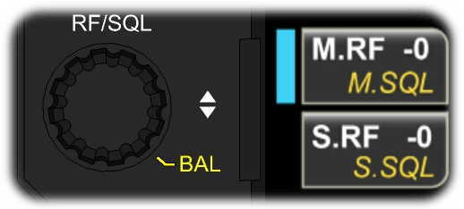
Rotate {RF/SQL} to adjust RF gain or squelch.
Tap the upper LCD button to adjust main receiver RF gain or squelch (blue indicator). Tap the lower LCD button to adjust sub receiver RF gain or squelch (green indicator). Tap a button a second time to alternate between its two functions.
Tapping the {RF/SQL} knob changes the LCD button selection.
Holding the {RF/SQL} knob turns on [BAL], allowing the SUB AF knob to set left/right balance (see AF Gain and Balance).
The inner concentric knob, {AF}, sets main receiver AF gain. The outer concentric knob, {SUB}, normally sets sub receiver AF gain. It can also be configured to control left/right channel audio balance (see RF Gain, Squelch, and Main/Sub Balance).
The LCD screen is divided into a number of elements as described below. Many of these elements show the current state of settings while also serving as touch controls.
Tap <?> (lower left-hand corner of the screen) to launch the built-in operating manual. You can then search for information on the current operation being performed by tapping <LAST CTRL>, or use the table of contents, or search by topic. For further details, see USING THE BUILT-IN OPERATING MANUAL.
Seven buttons along the lower edge of the display provide access to functions used frequently to configure and operate the K4: <MENU>, <Fn> (special functions), <DISPLAY>, <MAIN RX>, <SUB RX>, and <TX>. For a full description, see PRIMARY FUNCTIONS.
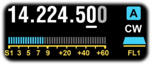
Adjacent to each VFO's numeric display is its ID (A in blue, B in green) and operating mode. Mode icons or the [MODE] switch can be tapped to change modes. See OPERATING MODES for per-mode operating instructions.
One digit in the frequency display is underlined, showing the present step size for VFO A or B knob rotation. You can tap digits in the numeric display to select a different step size. Alternatively, tap the [RATE] switch to alternate between 10 and 1 Hz, or hold [KHZ] to select a per-mode coarse tuning rate (as set by the VFO Coarse Tuning menu entry). To adjust the number of counts per turn of the VFO knobs, use MENU:VFO Counts Per Turn.
Tapping either VFO's MHz digits brings up the memory store/recall controls (see Frequency Memory Controls).
RIT and XIT share the same offset value, displayed in a box between the two S-meters. Tapping the box turns RIT on or off as an alternative to tapping the [RIT] switch. You can also left-click a mouse on the RIT or XIT icons to turn them on/off; a right click turns XIT on/off. See RIT/XIT and CLR for RIT/XIT usage information.
Each VFO has its own S-meter. For details, see TX AND RX METERING.
Tapping an S-meter switches to the min-pan for that receiver (see Mini-Pan).
During transmit, the S-meter associated with the transmit VFO is replaced by transmit bar graphs for power, SWR, ALC, and speech compression (in SSB and ESSB modes). These bar graphs use orange segments to distinguish them from the S-meters.
Normally the K4 transmits on VFO A, so these bar graphs will appear on the left. In SPLIT mode, the K4 transmits on VFO B, so they appear on the right. This serves as a clear reminder to the operator about whether SPLIT is in effect or not. Also see USING SPLIT.
Each receiver has its own filter bandwidth graphic, adjacent to its S-meter. This graphic shows the relative passband width and shift amount, which can vary per-mode. See RECEIVER SETTINGS for more information on filter settings.
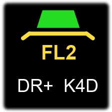
Beneath the filter graphic is the per-mode Filter Preset number (FLn). Tapping the graphic cycles through FL1/2/3, setting the passband to predefined values for each mode. An alternative is to tap the [FIL] switch above VFO A.
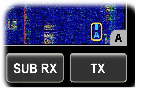
The K4D model includes a fully independent second receiver module (KRX4), with its own set of band-pass filters, preamps, and attenuators. The K4 will use this module whenever possible to maximize receive performance. When the KRX4 module is in use, the K4D icon (to the right of the RIT/XIT box) will illuminate. This is shown below. In this example the DR+ icon is also illuminated, indicating that MENU:RX Dyn. Range Optimization is turned on.
For further details, see DUAL RECEIVE.
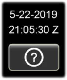
The status area, just above the Info button (<?>) at the lower-left corner of the screen, normally shows UTC date and time. Tapping this text brings up the STATUS DISPLAY button group, allowing you to select a different status display, such as your callsign and time, or supply voltage/current/power output/SWR, or main/sub signal levels in relative dB. See USING THE STATUS DISPLAY for full details.
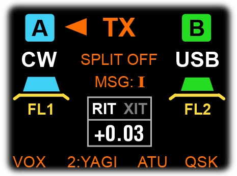
Icons associated with the transmitter are orange. As shown below, they are located above and below the RIT/XIT offset box.
"TX" and its arrows show which VFO is selected for transmit (see USING SPLIT). The VOX icon shows that VOX is on for the current mode (see VOX switch); ATU shows whether the ATU is in-line (ATU switch); QSK shows whether QSK (fastest break-in CW) is in effect (QSK switch).
The "MSG: I/II" icon, above the RIT/XIT box, shows which message bank has been selected for playback. When a message is playing back with auto-repeat, the icon changes to "MSG RPT" and flashes until repeat is cancelled.
The remaining transmit icon is the TX antenna indicator. It normally shows ANT 1/2/3, but it can also show a user-specified antenna name ("YAGI" in the example above, along with "2", the antenna number).
Also see ANTENNA SELECTION and TRANSMITTER SETTINGS.
Below each S-meter is a collection of icons pertaining to that receiver's configuration. These indicate the current settings of the preamps (PRE), attenuators (ATTN), noise blanker (NB), noise reduction (NR), audio peaking filter (APF), manual or automatic filtering (NTCH), automatic gain control (AGC), and receive antenna (e.g., ANT1 or RXANT1).
For details see RECEIVER SETTINGS and ANTENNA SELECTION.
The panadapter shows both a spectral display and waterfall. Single (VFO A or B) or dual panadapters can be shown. To adjust the panadapter's reference level, span, averaging, or other parameters, tap the <DISPLAY> primary function button, followed by the secondary function button for the target parameter.
You may also need to specify whether the operation is targeting the LCD or external display or both, and in dual-pan mode, whether the target is VFO A, VFO B or both. These selections are made using the two buttons groups that appear to the left of the parameter adjustment control.
For details, refer to the PANADAPTER section.
The mini-pan shows a narrow range of spectrum for fine-tuning of signals. (The data points are not simply magnified; they are resampled to ensure high resolution.) To display the mini-pan, tap the S-meter for either receiver.
In CW and PSK modes, AUTO-spot centers this signal by automatically adjusting the VFO frequency.
In FSK and AFSK modes, the mini-pan cursor identifies the mark tone, while a dotted line shows the space tone.
An alphanumeric keyboard is displayed when text entry is required, such as when entering your callsign (see Status Area) or CW/FSK/PSK message text (CW Messages).
In all cases, you may also enter text using an attached keyboard.
VFO A controls the frequency of the main receiver. Tap [RATE] to alternate between 1 and 10 Hz tuning, or hold [KHZ] to select a per-mode coarse tuning rate. You can also tap the kHz or Hz digits to directly select a tuning rate, or tap the MHz digits to bring up the memory recall window. See FREQUENCY MEMORIES.
To lock VFO A, tap [LOCK A]. To lock VFO B, hold [LOCK B]. When a VFO is locked, QSY via panadapter touch is also disabled.
Above the VFO A knob there are four LEDs:
• TX illuminates during transmit
• Delta-F (∆f) indicates that RIT, XIT or SPLIT is in effect
• SUB turns on if the sub receiver is in use (see DUAL RECEIVE)
• DIV turns on if diversity mode is in enabled (see DIVERSITY MODE)
Above VFO A is an array of 15 switches that comprise a numeric keypad (0-9, in orange labels). These can be used to enter frequencies and other numeric data when required. In addition to the decimal digits, there are three special functions: [X] (delete last-entered digit), [.] (decimal point), and [<-] (enter).
The keypad can be used to enter data in some menu entries, such as XVTR Band <n> RF. In this case a small keypad icon will appear to the right of the parameter edit field.
Additional functions of the keypad switches are covered below.
In CW and some data modes, tapping [SPOT] turns on a spotting tone at a per-mode pitch. The VFO can be adjusted until the signal pitch matches that of the spot tone. Use {XMTR} [MON] to adjust spot/sidetone volume. (To set LINE OUT sidetone level, use MENU:TX Monitor Level, Line Out.)
Auto-spot is also available. See Using SPOT and AUTO-spot.
Tap [MODE] (or tap the VFO A or B ID icons) to bring up the mode button group.
Most mode buttons can be tapped a second time to select an alternate mode. For example, if LSB mode is in effect, tapping the LSB button will switch to USB. Tapping CW will switch to CW-R (CW reverse mode). Alternate modes can also be selected using [ALT], the hold function of [MODE].
See OPERATING MODES for per-mode operating instructions.
Tap [FREQ ENT] to directly enter a desired VFO A frequency. To set the VFO B frequency, first tap [B SET], then [FREQ ENT].
Next, enter the desired frequency using the numeric keypad (Numeric Keypad). Entering 1 or 2 digits is interpreted as MHz; 3 or more digits as kHz. You can optionally include one or two decimal points during frequency entry (MHz and kHz).
To scan a selected range, you'll first need to create a frequency memory with VFO A and B as the start and end points. The stored value of VFO A's mode will be used. Next, hold [SCAN] to initiate scanning**. This will mute the receiver. A long hold (~3 seconds) will unmute the receiver and proceed with "live" scanning, which is useful when listening for weak signals on a very quiet band.
Also see BAND SELECTION.
Three switches above VFO A are used to control the VFOs:
• [A/B] swaps all of the settings of VFOs A and B
• [SPLIT] enters SPLIT mode (see USING SPLIT)
• [REV] swaps VFO A and B settings until the switch is released. This is useful for checking your transmit frequency in SPLIT mode when the sub RX is turned off.
• [A>B] copies the VFO A frequency to VFO B. A second tap of [A>B] within two seconds copies all settings, including preamp, attenuator, etc. If VFO A is on a different band than VFO B, then the RX and TX antenna selections are also copied. (To enable independent band selection for VFO B, set MENU:VFO B Different Band to YES.)
• [B>A] copies the VFO B frequency to VFO A. A second hold of [B>A] within two seconds copies all settings, including preamp, attenuator, etc. If VFO B is on a different band than VFO A, then the RX and TX antenna selections are also copied.
Tap [SUB] to turn on the sub receiver. When the sub is on, its frequency is controlled by VFO B, except in diversity mode, where both main and sub RX are placed on the frequency of VFO A (see DIVERSITY MODE). Sub receiver AF gain is controlled by the outer concentric knob to the left of the LCD.
VFO B/sub can be set to a different band from VFO A/main (see DUAL RECEIVE). In this case you may also wish to use dual panadapter mode (see PANADAPTER). To enable independent band selection for VFO B, set MENU:VFO B Different Band to YES.
The K4D model also allows the sub RX to use a different antenna from main; this is described in the ANTENNA SELECTION section. Separate antennas are required for DIVERSITY MODE, which is selected by holding [DIV]. This sets the sub receiver to the same band and frequency as VFO A, allowing the operator to hear the signal from the two antennas in left and right channel audio, often improving copy in fading conditions.
The middle row of switches above VFO A controls the most important receiver settings, including [PRE] (preamp), [ATTN] (attenuator), [NB] and [LEVEL] (noise blanker), [NR] and [ADJ] (noise reduction), [NTCH] and [MANUAL] (notch filter), [FIL] (filter preset), and [APF] (audio peaking filter). Tap [B SET] to set up the sub receiver.
For detailed information on these controls, see RECEIVER SETTINGS.
In CW, PSK, and FSK modes, tapping [M1]-[M4] plays recorded message text. Holding [M1]-[M4] does auto-repeat for both text and DVR messages. Tap [REC] to enter message text; this brings up the built-in alphanumeric keyboard. Also see CW Messages.
In speech modes, the message play and record buttons activate the DVR (digital voice recorder). See DIGITAL VOICE RECORDER (DVR).
Tapping [RCL] or [STORE] brings up the frequency memory selector, which provides 200 general-purpose memories. There are also 4 Quick Memories per band, accessed by tapping [M1]-[M4] after tapping [RCL] or [STORE].
For details see FREQUENCY MEMORIES.
The K4 can record and play received audio. Both main and sub audio are recorded and played if the sub receiver was on during record. To bring up receive audio record/play controls, hold [AF REC] or [AF PLAY]. See Recording and Playing Receive Audio.
The VFO B knob (upper right-hand corner of the front panel) sets the frequency of VFO B.
Just below the VFO B knob is [B SET], the VFO B SET switch. When [B SET] is tapped, the B SET icon turns on, just above the RIT/XIT box at the upper middle of the LCD. B SET allows you to directly set up VFO B and the sub receiver. (Tap [B SET] or the icon again to exit.)
For example, the tuning rate for VFO B can be set by tapping [B SET], then tapping [RATE] or holding [KHZ]. VFO B's frequency can be directly set by tapping [B SET], then [FREQ ENT]. B SET can also be used to set up the preamp, attenuator, filter bandwidths, and other VFO B/sub settings.
Also see RECEIVER SETTINGS, BAND SELECTION, and DUAL RECEIVE.
Tap [RIT] to turn on Receive Incremental Tuning, then rotate the OFS (offset) knob below the switch to tune in a signal. RIT offsets only your receive frequency, not transmit. It is especially helpful when CW stations call you off-frequency.
Similarly, [XIT] can be turned on to adjust only your transmit frequency. One use for XIT is to quickly move the VFO off-frequency for doing ATU tuning. This avoids causing QRM (interference) to other stations.
Tap [CLR] to set the RIT/XIT offset frequency to zero.
You can also left-click a mouse on the RIT or XIT icons to turn them on/off; a right click turns XIT on/off.
Also see RIT Knob Alt. Function and RIT CLR 2nd Tap Restore.
[PF1]-[PF4] are user-programmable function switches, primarily used to quickly access often-used menu entries. For example, by default holding [PF1] takes you directly to MENU:LCD Brightness. PF1-PF4 menu assignments can be changed by locating a menu entry of interest, then hold the desired PFn switch.
If the menu parameter assigned to a switch is binary (i.e., has only two settings), then holding the PFn switch will not bring up the menu. Instead, it will select the alternate value, then flash a brief message to display it.
Each of these switches can, alternatively, perform nearly any combination of radio functions. See MACRO PROGRAMMING.
_________________________________________________
This section emphasizes setup and operating procedures. You may wish to review the Key to Text Styles.
** Indicates a feature that is still in development.
Before putting your K4 on the air, you should become familiar with the primary function buttons located at the lower edge of the LCD screen. These functions, used for basic setup of transmit, receive, and panadapter operation, are described below.
New HF operators will find the defaults to be satisfactory in most cases.
Also see Introduction to the Elecraft K4.
Tapping <MENU> brings up a list of settings that are infrequently changed. The entries are in alphanumeric order.
Using VFO A or the up/down arrows, scroll to highlight the desired menu entry. Tap the lock symbol (if present) to unlock it, then tap the parameter field. Use VFO A or the up/down arrow buttons to adjust the value. In some cases a small keypad icon will appear, indicating that the numeric keypad switches above the VFO may be used to enter the highlighted parameter.
Tap <NORM> to use the default value. For a full list of menu entries, see IV. MENU LISTING.
Programmable function switches [PF1]-[PF4] can be assigned to often-used menu entries. See PF1-PF4.
The <Fn> switch provides access to up to 14 special functions, some of which are pre-defined, such as <DX LIST>. F1 through F8 can execute user-defined command sequences or macros; see MACRO PROGRAMMING.
The following special functions are available. Other special functions will be added as they become available.
Tap <Fn>, then <SCRN CAP> to capture the content of both the LCD and external monitor into two separate files. You'll need to have a USB flash drive installed in one of the three USB A jacks. Also see MENU:Screen Cap File. Note: There is no "eject" control for the flash drive, as required on some computers. The K4 mounts/unmounts the flash drive (from a software perspective) as needed.
Tap <Fn>, then <MACROS> to enter the macro editor. This can be used to create user-defined macros for Fn > F1 through F8. Also see MACRO PROGRAMMING.
Tap <Fn>, then <SW LIST> to see a list of all software components and their currently installed revisions. At the top of the screen, in parentheses, is the overall release number (e.g., R22).
Tap <Fn>, then hold <UPDATE> to go to the K4 software update screen. Tap the <?> button for detailed instructions on how to update software or restore an earlier version. An ethernet connection is generally required for this purpose, though it's also possible to load from a USB flash memory device. In the latter case, the flash memory device must be pre-loaded with the intended software release.
Tap <Fn>, then <DX LIST> to bring up a complete list of countries and prefixes. Scroll the list using VFO A or the up/down arrow buttons. (The list is updated periodically in conjunction with software updates.)
To search for a country or prefix, tap the magnifying glass button. This will bring up the built-in alphanumeric keyboard. Enter text to search for, then tap ENTER. If there are multiple hits, the magnifying glass and up/down buttons will remain illuminated, indicating match navigation mode is in effect. Tap the up/down buttons to search through matches. Tap the magnifying glass button to exit match navigation.
Tap <Fn>, then hold <BACKUP> to use the configuration backup utility. A USB flash memory device must be plugged into one of the USB-A jacks.
You can select whether to backup or restore six categories of data, including General Configuration, Frequency Memories, PF Key and K-Pod Macros, CW/PSK/FSK messages, DVR messages, and Diagnostic Logs.
For further instructions or troubleshooting of this function, tap the "?" button.
Tap <DISPLAY> to set up the panadapter. This will bring up two rows of controls. The lower row is comprised of various DISPLAY functions, such as REF LVL, SPAN, etc. The upper row has three controls: (1) LCD/EXT display target selector; (2) A/B panadapter target selector; and (3) parameter adjustment.
In the simplest case, with only a VFO A panadapter in use and no external display, the LCD/EXT target can be set to LCD, and the A/B target can be set to (A). You can then adjust the selected secondary parameter.
For a description of all panadapter functions, see PANADAPTER, below.
Tap <BAND> to choose 160-6 m, GEN (SWL band), MEM (recent frequency memories used), or XVTR (one or more transverter bands). For complete details on band and frequency selection methods, see BAND SELECTION.
To configure the main receiver, tap <MAIN RX>, then tap the desired secondary function. Most of these functions are common to all operating modes; exceptions are noted below.
<ANT CFG>: Specifies behavior of the RX ANT switch. See ANTENNA SELECTION.
<RX EQ>: Receiver 8-band graphic equalizer.
<LINE OUT>: Sets up LINE OUT audio levels. Left and right-channel output can be set independently, or you can tap <LEFT=RIGHT> to set both to the value of the left channel.
Note: Windows Sound Control Panel does not accurately show sound input level. The correct levels are shown by WSJT, MMTTY, and other apps.
<VFO LNK>: Turns VFO B to VFO A linking on/off. The link icon is to the right of the VFO B ID icon. VFO B is set to the same frequency as VFO A, normally, but you can also offset VFO B by any desired amount, which will be preserved as VFO A is tuned.
<AFX>: Turns audio effects on or off. Holding this button selects the AFX mode: DELAY (simulated stereo) or PITCH (low-to-high audio pitch mapping from left to right when used with stereo headphones or dual external speakers).
<AGC>: Selects AGC slow (AGC-S) or fast (AGC-F) for the current operating mode. Holding this button turns AGC on or off (AGC-). Also see MENU:AGC Decay, Fast and MENU:AGC Decay, Slow.
Note: When AGC is off, protection from excessive audio levels is provided by an audio limiter (AF Limiter).
The remaining <MAIN RX> secondary functions are defined for some operating modes, as described below.
<APF BW>: Sets the bandwidth of the audio peaking filter to 30 or 50 Hz. 30 Hz provides greater noise rejection, while 50 Hz allows for faster code speeds.
<TEXT DECODE>: Tap this button to turn text decode on/off and set the number of receive text lines. Threshold defaults to AUTO, but you can select a fixed value threshold value to minimize decoding of noise as characters. Also see CW Text Decode and Built-In Data Modes.
<TEXT DECODE>: Same as CW text decode, but without variable threshold.
The <SUB RX> button group provides access to the same secondary functions as <MAIN RX>, except that the operating mode of VFO B/sub RX applies.
You can also tap <SUB RX> as an alternative to tapping the [B SET] switch. Both enter B SET mode, switching the multifunction knobs and other per-VFO controls to target VFO B/sub RX. Tap [B SET] or <SUB RX> again to exit B SET mode.
To configure the transmitter, tap <TX>, then tap the desired secondary function. Most of these functions are common to all operating modes; exceptions are noted below.
<ANT CFG>: Specifies behavior of the ANT switch (transmit antenna). See ANTENNA SELECTION.
<TX EQ>: Transmit 8-band graphic equalizer. TX EQ only applies in voice and CW modes.
<LINE IN>: Sets up LINE IN sources and audio levels. You can select SOUNDCARD (digital audio via the USB type B jack) or LINE IN (analog audio jack). Each can have a different level.
<MIC INP>: Tap this button to select the microphone audio source (front mic, rear mic, LINE IN, or a combination of these).
<MIC CFG>: Sets up front/rear mic gain and bias. For the front mic only, configures buttons (NONE or UP/DN). For an Elecraft MH4 mic, turn bias on, set preamp gain to 0, and enable all buttons. Mics with low-output elements may require higher preamp gain settings.
<VOX GN>: Sets audio-operated transmit sensitivity. This only applies in voice modes or applicable data modes (DATA, AFSK), with [VOX] turned on.
<ANTIVOX>: Sets anti-VOX level. The higher the level, the less likely that audio from the K4's speaker(s) will trigger voice transmit.
The remaining <TX> secondary functions are defined for some operating modes, as described below.
The following settings apply to the internal keyer. They apply to FSK and PSK modes as well when used conversationally with the internal keyer and message memories.
<PDL>: Selects keyer paddle normal (jack tip = DOT) or reverse (tip = DASH).
<IAMB>: Selects the desired Iambic keying mode. The default is mode A (IAMB A), which is generally considered easier by many CW users. Mode B (IAMB B) may be preferred by operators who learned to do "squeeze-keying" with another keyer having this or a similar mode. Both modes provide dot and dash memories--enabling fast code speeds--but with slightly different "element-insert" timing.
<WEIGHT>: Sets the dot/space ratio. For most users, a value of 1.15 to 1.20 is ideal.
Note: Low values of weight may result in a dot/space ratio that sounds too "staccato" on the air. Do not use a lower value of weight, then try to compensate by setting MENU:TX DLY Key Out to RF Out to a high value. TX DLY is intended for use with external amplifiers, not as a means of adjusting keyer timing.
<SSB BW>: Sets SSB transmit bandwidth. A narrower bandwidth will reduce fidelity but reduce QRM to other stations in crowded conditions. The default is 2.9 kHz. Note: When ESSB is on (see below), the SSB BW button label changes to ESSB BW.
<ESSB>: Turns ESSB mode on/off (Extended Single Sideband) and allows you to set the ESSB bandwidth. This value is independent of the normal SSB bandwidth. The default is 4.0 kHz.
<AM BW>: Sets the transmit bandwidth for AM mode.
<RPT>: Selects simplex or +/- offset for repeater use.
<RPT OFS>: Used to specify a per-band offset for use with repeaters.
<PL TONE>: Used to set up PL tone encode for use with repeaters.
<DTMF>: Brings up a DTMF keypad and a set of 6 programmable tone commands. To create a tone command, hold the desired CMD button, then enter the DTMF sequence. To play a tone command, or to use the DTMF keypad directly on-air, you must first enter transmit mode via either PTT or the XMIT switch. Also see FM Operation.
<DATA BW>: Sets the transmit bandwidth for DATA mode. This mode is used for FT8 and most other audio-based data modes. Also see DATA MODES.
The K4 provides several ways to select the band and operating frequency:
• Tap <BAND>, then tap the button corresponding to the desired band. Tapping a given band button more than once cycles through three band-stacking registers, recalling recently used frequencies and modes. Tapping the <GEN> band button returns to the most recently used SWL or general-coverage frequency, typically outside any ham band. Tapping <MEM> is a shortcut to the most recently used frequency memories. <XVTR> takes brings up the array of 12 transverter band buttons.
• Tap [FREQ ENT] and directly enter the desired numeric frequency. (Examples TBD.) When you're on a transverter band, values with three digits and higher are interpreted as MHz. On HF-6 meters, they are interpreted as kHz. If [B SET] is tapped first, the entered frequency will be used to set up VFO B.
• Tap [RCL] to bring up the frequency memory selection window. You can either scroll to a desired memory and tap the <RCL> touch button, or tap one of [M1]-[M4] to recall a quick memory.
• Tapping the MHz digits of either VFO also brings up the memory recall window.
To select a transmit antenna, tap [ANT]. An orange text icon near the upper middle of the LCD shows this selection. Both receivers default to this antenna as well, as indicated by their separate antenna icons under the main and sub S-meters.
If there's no KAT4 ATU installed, only ANT 1 will be available for HF-6 meter use. With a KAT4 installed, ANT 1, 2, and 3 are available. If you have only two antennas rather than three, you can constrain the ANT switch to alternate between them. To make these selections, tap <TX>, followed by <ANT CFG>.
When using external transverters, IF drive is provided at the XVTR OUT jack. Internal transverters use ANT4.
Also see ATU TUNE.
By default, the transmit antenna is also used for the main and sub receivers. The receivers can be switched to receive-only antennas by tapping [RX ANT] (for main) or holding [SUB ANT] (for sub). This brings up the RX antenna button group, which includes various selections (per-receiver):
• ANT1, ANT2, and ANT3 (if an ATU is installed)
• RX ANT 1 and XVTR IN/RX ANT 2 (dedicated receive antennas)
• "=TX", which causes a receiver to always use the transmit antenna
• "=OPP TX ANT", which causes a receiver to use the opposite of the transmit antenna if the transmit antenna has been constrained to a subset. (To set up the latter, tap <TX>, then <ANT CFG>.) This mode is useful for diversity operation where both antennas used for diversity are connected to ANT 1/2/3.
There are two considerations to keep in mind when using the ANT 1, 2, and 3 selections for receive purposes:
• The current TX antenna is identified by an orange dot on the associated ANT button in the RX antenna button group. Selecting this antenna for receive is equivalent to using the =TX selection, i.e. the signal passes through the ATU's L-network. But if you later switch to a different transmit antenna, this will no longer be the case. The orange dot moves to another button, and the ATU will now treat the selected RX antenna as receive-only. The receive signal will no longer pass through the L-network.
• Only one of the three ATU antennas can be used as a receive-only antenna at a given time. For example, you cannot select ANT1 for TX, ANT2 for main RX, and ANT3 for sub RX. If both receivers are set up to use ATU antennas for receive, the most-recent ANT1/2/3 receive-antenna selection will be applied to both receivers. This will be reflected in their associated antenna icons.
Alternative ways to put the two receivers on different antennas: (1) Use the RX ANT IN 1 or 2 inputs instead of ATU antennas for one or both receivers. (2) Set one of the receivers to =TX ANT. This will allow the other to use either of the non-transmit ATU antennas for receive. (3) Set one receiver to =TX ANT and the other to =OPP TX ANT. This requires that a two-antenna subset be specified for the transmitter using the <TX> <ANT CFG> function.
Note: On a basic K4, both receivers will always share the same antenna. The K4D adds a second band-pass filter unit and a second A-to-D converter, allowing the sub receiver to use a different antenna from main. These modules can be installed in a basic K4 at any time, converting it to a K4D.
Both the ATU antennas and receive antenna jacks can be given names by the user, e.g. "Yagi," "Dipole," etc. These names will then appear as the TX and RX antenna icons in lieu of the default names (ANT1, 2, 3 and RX ANT 1, 2).
RX ANT OUT provides a way to insert an external band-pass filter, preamp, attenuator, or antenna splitter into the receive path of the main and sub receivers. Another possible use is to feed a signal to an adjunct receiver/panadapter. The signal that appears on RX ANT OUT is obtained from the transmit antenna path, meaning it passes through the ATU and TX low-pass filters. Since it also passes through the T/R switch, it is inherently protected from the K4's own transmit signal.
In order for RX ANT OUT to be active, both receivers must be configured to use receive-only antennas (RX ANT IN 1 or XVTR IN/RX ANT IN 2). This disconnects the T/R switch's receive path from both receivers so that it may be routed to RX ANT OUT instead.
Example: If you wanted to insert a narrowband filter for 20 meters into the path of the main and sub receivers, you could connect its input to RX ANT OUT and its output to RX ANT 1 IN. To enable the RX ANT OUT signal, set up the main and sub receivers to use RX ANT 1.
Additional examples TBD.
Signals below about 1 MHz will be attenuated when the receiver is using the transmit antenna path (i.e., when the RX antenna is set to the "=TX" setting, or to an ATU antenna also being used by the transmitter). This is due to the high-pass filter incorporated in the T/R switch, which protects the PIN diodes. To listen to signals below 1 MHz without attenuation, use a separate receive antenna connected to RX ANT 1 IN or XVTR IN/RX ANT 2 IN, or select an ATU antenna that is not in use by the transmitter. (The current transmit antenna is indicated by its icon, as well as an orange dot in the RX antenna button group.)
This section discusses basic setup procedures for each of the operating modes.
The {XMTR} and {FILTER} multi-function knobs are used to adjust frequently changed parameters such as mic gain or CW code speed, while the <MAIN RX>, <SUB RX>, and <TX> primary function buttons on the LCD are used to do per-mode configuration.
You can select the desired mode for a given VFO in one of two ways:
• tap the mode icon adjacent to its numeric display
• tap the [MODE] switch (above the VFO A knob). This normally selects the mode for VFO A; tap [B SET] first to select the mode for VFO B.
Either method brings up the mode button group.
Most modes also have an alternate setting, selected by tapping the target mode's button a second time. For example, tapping <CW> a second time switches to <CW-R> (CW reverse). Tapping <LSB> switches to <USB> and vice-versa. Alternate modes can also be selected using [ALT], the hold function of [MODE].
A key, keyer, or other keying device must be connected to the KEY input on the rear panel. To set up keying via a computer, see USB and RS-232.
A paddle directly connected to the PADDLE input takes advantage of the K4's built-in keyer function, eliminating the need for an external keyer. This also allows your own CW to be displayed in the text-decode window. You can use the paddle to transmit in FSK and PSK modes, as well, by sending CW characters.
CW can be sent while in SSB modes. This feature must be enabled using the CW TX in SSB Mode menu entry.
• Keyer speed is set using {XMTR} <WPM>.
• To set the desired sidetone pitch, use {XMTR} <PTCH>. Note: Sidetone pitch is adjustable in 10 Hz steps. However, selecting a pitch that's a multiple of 50 Hz will provide better passband alignment when IIR filters are enabled. See MENU: RX CW IIR Filters (50-200 Hz).
• Sidetone volume is adjusted by holding the {XMTR} knob to select its [MON] function (monitor). To set the LINE OUT sidetone level, use MENU:TX Monitor Level, Line Out.
• To practice sending CW without putting out any power, hold [TEST] to enter TX test mode. The TX icon will change to TX Test.
• To use hit-the-key transmit, [VOX] must be turned on. If VOX is off, you'll need to tap XMIT to enter transmit mode, or use a foot switch or other device connected to the PTT IN jack.
• For fastest break-in, turn on [QSK]. For more casual QSOs, you may wish to leave QSK off, resulting in slightly slower receive recovery between elements, thus a less "busy" sound during keying. When QSK is off, {XMTR} <DLY> sets the receive recovery delay in .01-second steps.
• Other CW settings (paddle normal/reverse, iambic mode, and keying weight) can be accessed by tapping <TX>. See TX primary function control, above.
The K4 provides both manual and automatic signal spotting in CW mode, allowing you to match the pitch of stations you call.
In CW, FSK, and PSK modes, tapping [SPOT] turns on a spotting tone at a per-mode pitch. The VFO can be adjusted until the signal pitch matches that of the spot tone. Use {XMTR} [MON] to adjust spot/sidetone volume.
Auto-spot is also available. Using [AUTO] while a signal is in the passband will cause the VFO to move toward the signal. (Auto-spot can correct a tuning offset of up to about +/- 100 Hz.) If the mini-pan is displayed (by tapping the S-meter), you should see the signal line up with the mini-pan's center tuning line.
The K4 provides 2 banks of 4 message buffers each for use in CW, PSK, and FSK modes. These messages can be backed up using Fn > BACKUP.
To use CW message buffers:
• Tap [REC] to enter message text; this brings up the built-in alphanumeric keyboard. You'll be prompted to tap M1..M4 before entering your text. Further information about the keyboard appears below.
• To select the second set of 4 messages, hold [BANK]. The bank number (I or II) will appear in the keyboard prompt during message record.
• Tapping [M1]-[M4] plays recorded message text; tapping a message switch while another message is playing "chains" the new message onto the present one. Holding [M1]-[M4] does auto-repeat. The auto-repeat interval is set using MENU: Message Repeat Interval.
• To cancel message play, tap [REC], [XMIT], [TUNE], or the keyer paddle.
• During auto-repeat, the message bank icon changes to "MSG RPT" and flashes as a reminder.
• Prosigns can be entered into CW/data messages using the following punctuation marks:
( "KN" + "AR" = "BT" % "AS" * "SK" ! "VE"
• The built-in keyboard includes two special characters for use in FSK and PSK modes: EOL and EOT. EOL inserts a CR/LF sequence, allowing messages with formatted lines. EOT can be placed at the end of the message to terminate the usual 4 seconds of nul characters or "diddles." (EOT actually inserts a '|' character; this can be entered when using an attached keyboard to send text.) EOL and EOT characters appearing in messages have no effect in CW mode.
The K4 can decode transmitted and received CW signals, displaying the text in multiple lines below the panadapter. This can be useful for learning CW, for copying higher code speeds, or even for the benefit of a non-CW-operator looking over your shoulder.
To enable this feature:
• tap <MAIN RX> or <SUB RX>, then tap <TEXT DECODE>
• select 1 or 3 lines of receive text
• the recommended threshold setting is AUTO, though in some band conditions there may be an advantage in selecting one of the fixed thresholds (1-9)
The K4 will decode CW from both receivers simultaneously, using separate windows, if both are configured for text decode (you can also decode CW from one receiver while decoding PSK or FSK on from the other).
Characters sent with the keyer paddle or an attached keyboard will appear on the text decoder's TX line.
The K4 can obtain voice audio from the front mic, rear mic, or LINE IN (analog or digital), or a combination of these. These selections are made by tapping <TX>, then <MIC INP>. Some operators prefer to use a rear-panel mic to eliminate clutter at the front panel.
For a complete list of mic and line settings, refer to the TX function section.
Transmit is normally initiated by the mic PTT (push-to-talk) switch, [XMIT] switch, or [VOX] (voice-operated relay). You can also use a foot switch, computer or other device to engage PTT. See descriptions of the PTT IN, USB, RS-232, and ACC jacks.
It is possible to send CW while in SSB modes. For details refer to the CW TX in SSB Mode menu entry.
Before transmitting in voice modes, you'll need to properly set up voice monitoring, mic gain, compression, and power level. These are covered in the following sections. For this purpose, VOX should be turned off.
Voice monitoring allows you to hear the way you’ll sound on the air with your selected mic gain, compression, and TX EQ settings. To set up voice monitoring:
• Hold [TEST] to put the K4 in TX TEST mode, so you won’t be transmitting. The TX icon will change to TX Test.
• Set {XMTR} <MIC> high enough to hear your voice (typically 10-20).
• Press your mic’s PTT switch or tap [XMIT].
• Hold the {XMTR} knob to enable [MON] adjustment. While speaking into the mic, set the desired level. Tap {XMTR} again to exit the [MON] function.
• To set the LINE OUT voice monitor level, use MENU:TX Monitor Line Out.
• Exit transmit (release PTT, or tap XMIT again).
To set up mic gain and compression, follow the instructions below. Note: Speech compression only applies to SSB and ESSB modes.
• Adjust the monitor level if necessary (see previous section).
TX TEST mode is recommended during the following adjustments so a signal is not transmitted. This will not affect your CMP/ALC bar graph readings. To enter TX TEST mode, hold [TEST]. The TX icon will change to TX Test.
• Set {XMTR} <CMP> to 0. This turns compression off for mic gain adjustment.
• While speaking into the microphone in a normal voice, adjust {XMTR} <MIC> for a peak ALC meter indication between "5" and "7".
• Adjust {XMTR} <CMP> for the desired speech compression level while speaking. When you speak, the CMP bar graph shows approximate compression amount. Typically, a CMP value of 0 to 10 is used for casual QSOs, while higher compression is used if band conditions require extra "punch."
IMPORTANT NOTE REGARDING EXTERNAL AMPLIFIERS: The K4 uses an advanced speech compression algorithm, plus Controlled Envelope Single Sideband (CESSB). CESSB is turned on with any non-zero setting of CMP. When CMP is set to maximum (30), average talk power will be increased by as much as 8 dB. This increase will also apply to any external amplifier, potentially increasing its average power dissipation, current drain, and temperature. Be sure to observe all manufacturer limits when using maximum CMP values along with maximum amplifier power output.
• If you were in TX TEST mode, return to normal operation by holding [TEST].
• If you had PWR set to 0, set it for the desired level. Key the rig again and verify that you have about the right power output level.
In speech and audio data modes, the [VOX] switch enables or disables voice-activated (or audio-activated) transmit. VOX sensitivity and anti-vox controls can be accessed by tapping <TX>, then <VOX GN> and <ANTIVOX>.
To set up VOX:
• VOX gain should be set to trigger at normal speech levels, but not in response to incidental noise. Start with low settings (5-10).
• ANTIVOX sets VOX immunity to receiver audio coming from the speaker(s). With the mic closer to the speaker than normal, increase ANTIVOX until the K4 doesn’t switch to TX mode when listening to a strong signal.
• Adjust the VOX delay using {XMTR} <DLY>. A longer value will keep the K4 in transmit mode for a longer period of time, allowing for pauses in speech.
The noise gate function mutes mic audio below a selected threshold; this may be useful in noisy environments. See MENU:TX Noise Gate Threshold.
To setup for repeater use:
• Hold [ALT] switch to select simplex, TX up (FM+), or TX down (FM-). You can also change this setting using <TX> <RPT mode>.
• Set up repeater offsets using <TX> <RPT OFS>.
• Set up VFO coarse-tuning step size using the VFO Coarse Tuning menu entry.
• Set up PL tone encode pitch and on/off using <TX> <PL TONE>.
• To set up voice and PL tone deviation, use FM Deviation, Voice and FM Deviation, Tone.
• DTMF tones (dual-tone, multi-frequency) can be transmitted in FM mode. Use <TX> <DTMF> to bring up the DTMF window. Hold PTT, tap digits or symbols on the provided keypad, then release PTT. You can also create stored DTMF commands. Hold <CMD1> - <CMD6> to enter a sequence. Tap the return arrow to complete entry. The CMD button can then be tapped to play the sequence back (while PTT is asserted).
The K4 has four data modes: DATA, AFSK, FSK, and PSK. These are further described below.
There are also manual sections dedicated to setup requirements for RTTY (RTTY CONFIGURATION) and FT8/JT/etc. (FT8 / JT / ETC. CONFIGURATION).
The K4's built-in data modes include FSK (RTTY) and PSK (PSK31 or PSK63). In these modes, you can turn on text decode to have demodulated characters appear on the display. You can also transmit in data modes using your keyer paddle or with a keyboard connected to any of the USB type A jacks.
To enable text decode and paddle/keyboard transmit:
• select PSK (PSK31/PSK63) or FSK (RTTY) mode on either the main or sub receiver (or both)
• tap <MAIN RX> or <SUB RX>, then tap <TEXT DECODE>
• select 1 or 3 lines of receive text
The K4 will decode PSK or FSK from both receivers simultaneously, using separate windows, if both are configured for text decode. You can also decode CW from one receiver while decoding PSK or FSK on from the other.
Characters sent with the keyer paddle or an attached keyboard will appear on the text decoder's TX line. You can also use the CW message memories, [M1]-[M4], to send text.
The K4 provides a rich set of I/O connections for use with computer-based data modes, including analog LINE IN/LINE OUT (LINE IN and LINE OUT jacks) and remote control/digital data interfaces (USB, RS-232, and ACC).
For general information on setting up these ports for data input/output, see TX and MAIN RX primary functions.
Audio-based data communications (via LINE IN/LINE OUT or USB soundcard) can be done using LSB or USB mode. However, DATA and AFSK modes offer several benefits not available in SSB modes (see below).
Note: If you prefer to use LSB or USB for audio data, you’ll need to manually set CMP to 0 to prevent data signal distortion. Refer to your data communications software manual to determine how to set up the VFO and computer for accurate frequency display.
To select a data mode, tap [MODE] or the mode icons adjacent to each VFO to bring up the mode button group.
The following modes are available:
• DATA (generic) can be used for all audio-based data modes, including FT8, JT modes, PSK31/PSK63, MFSK, AFSK, etc. The VFO displays the suppressed-carrier frequency, just as when SSB modes are used for data. USB is “normal” for DATA A. Compression is internally set to 0. For detailed FT8/JT/etc. setup instructions, see FT8 / JT / ETC. CONFIGURATION.
• Like DATA mode, AFSK is also audio-based, but optimized for RTTY. The VFO displays the RTTY mark frequency, and LSB is “normal”. The built-in text decoder can be used in this mode. Compression is internally set to 0.
• FSK is identical to AFSK, except that direct modulation is used, via an FSK data input pin, an attached keyboard, or the keyer paddle (see Built-In Data Modes). The text decoder can be used in this mode. For detailed FSK/RTTY setup instructions, see RTTY CONFIGURATION.
• PSK is a direct-transmit mode for PSK31 and PSK63. Like FSK mode, it can be used with the text decoder as well as a keyboard or keyer paddle. You can also use auto-spot with PSK mode.
In AFSK, FSK, and PSK modes, multiple data speeds are available. For PSK: PSK31 and PSK63. For AFSK and FSK: 45 and 75 baud.
If you’re using an audio-based data mode (LSB, USB, DATA, or AFSK), you’ll need to set the transmit audio input level while watching the ALC meter. You can use the same procedure outlined for voice modes, above, except that speech compression should be set to 0 if you're using an SSB mode. ALC deflection should be kept to just below the "5" level on the ALC meter in modes where low IMD is critical, such as FT8.
(Note to those who have used a K3: The K4's bar graphs have twice as many bars as the K3's for a given activation level. The K3 manual suggested "4 bars" as the right level for data modes, which would translate to 8 bars on the K4. But it's easier to simply stay just below the "5" mark on the K4's ALC meter.)
In all cases (SSB modes as well as DATA), you can optionally use the transmit monitor to listen to your data signals. The procedure given for voice modes can be used. Monitor levels for voice and DATA modes are independent.
To set LINE OUT transmit monitor level, see MENU:TX Monitor, Line Out.
Prior to using the receiver, you should familiarize yourself with the receive configuration functions (MAIN RX and SUB RX). These are used to configure RX EQ, LINE OUT, audio effects, text decode, and various per-mode settings.
The following controls are used during normal operation to optimize receiver performance under different conditions.
You may wish to review how the FILTER and RF/SQL multifunction knobs are used; see MULTI-FUNCTION CONTROLS.
The preamp and attenuator controls establish the gain or loss ahead of the receiver circuitry, namely the A-to-D converter(s). Higher gain will generally improve receiver sensitivity, within the limits of your station's noise floor. Lower gain or added attenuation will reduce the possibility of receiver overload in the presence of extremely strong signals.
• Preamp (PRE): Tap [PRE] to cycle through preamp OFF, PRE1, and PRE2. PRE2 provides the highest gain and lowest noise figure on a given band. On 12, 10, and 6 meters, there's an optional PRE3 setting that provides an even lower noise figure for extreme weak-signal work. To enable PRE3, use MENU:Preamp 3 (12/10/6).
• Attenuator (ATTN): Hold [ATTN] to bring up the attenuator controls (on/off and level). Attenuation varies from 0 to 21 dB in 3 dB steps.
AF gain is set using {AF/SUB}, a dual-concentric control to the right of the mic jack.
• Rotate the small inner concentric knob to adjust main receiver AF gain.
• Rotate the large outer concentric knob to adjust sub receiver AF gain.
These settings are adjusted using the {RF/SQL} knob.
The default value for the RF gain controls is 0 (no reduction in RF gain). Counter-clockwise rotation of the knob increases attenuation (reduces gain) from 0 to -60 dB.
Some operators prefer to control receiver gain using the RF gain control rather than AF gain control, in order to keep signals from activating AGC. AGC can even be turned completely off, in which case manual RF gain reduction becomes mandatory. (To turn AGC off, tap <MAIN RX> or <SUB RX>, then hold <AGC>. When AGC is off, the MENU:AF Limiter setting applies. Adjust to the desired signal clipping threshold.)
• To adjust main receiver RF gain, use {RF/SQL} <M.RF>.
• To adjust sub receiver RF gain, use {RF/SQL} <S.RF>.
The default value for the squelch controls is 0 (squelch completely open). Squelch is usable in all modes.
• To adjust main receiver squelch, use {RF/SQL} <M.SQ>.
• To adjust sub receiver squelch, use {RF/SQL} <S.SQ>.
Hold the {RF/SQL} knob to access the [BAL] (balance mode) controls. Tapping the <SUB AF> button changes its label from = NOR (normal) to = BAL. This assigns the SUB AF gain knob (below RF/SQL) to left/right audio balance control; the MAIN AF knob then sets overall gain for both receivers. When balance mode is off (SUB AF = NOR), the SUB AF knob assumes its normal function, control of sub receiver audio level.
The filter passband is shown visually by graphics adjacent to each S-meter. The {FILTER} multifunction knob is used to set passband width and shift (or hi-cut/lo-cut) on a per-mode basis.
Tap the knob to alternate between <BW> (or <HI> cut) and <SHFT> (or <LO> cut). Hold the knob to select the [NORM] (normalized) passband for each mode. When the passband is normalized, two "wings" appear on each side of the filter graphic as shown below:
Additional information on filter controls:
• {FILTER} controls normally apply to the main receiver. To target the sub receiver directly, tap [B SET] or <SUB RX> first.
• Filter Preset (FIL): Tap [FIL] to cycle through presets 3/2/1 (wide, medium, narrow). You can also select presets by tapping the filter bandwidth graphic adjacent to each S-meter.
• Audio Peaking Filter (APF): Hold [APF] to turn the CW audio peaking filter on/off. To choose narrow (30 Hz) or wide (50 Hz) APF bandwidth, tap <MAIN RX> or <SUB RX>, then tap <APF BW>.
The following three controls can be used to reduce noise and interference.
Note: Since the K4 is an SDR (software-defined radio), new noise remediation algorithms can be added as they become available.
• Noise Blanker (NB): Tap [NB] to turn the noise blanker on/off, or hold [LEVEL] to bring up the noise blanker controls (on/off, filtering mode, and level). As with all noise blankers, you should use the lowest effective setting to minimize any audible artifacts. If you hear audio artifacts such as "pumping" or modulation when the NB is turned on, try changing the NB filter mode from "NONE" to "NARROW" or "WIDE". This will remove QRM ahead of the noise blanker. The optimal level setting may be different when the NB filter is engaged.
Note: The panadapter has its own noise blanker, affecting only the behavior of the display. Use <DISPLAY> <NB> to select its mode. If the panadapter blanker mode is AUTO, then it will turn on whenever the receiver's noise blanker is turned on.
Noise Blanker Tip: On extremely noisy bands, the noise blanker will often be far more effective if front-end gain is reduced. Try turning off the preamp and even turning on the attenuator. This can keep noise from hitting the AGC threshold, resulting in a much greater audible difference between NB ON vs. OFF.
• Noise Reduction (NR): Tap [NR] to turn noise reduction on/off; hold [ADJ] to adjust the noise reduction settings.
• Auto-Notch (NTCH-A): Tap [NTCH] to turn auto-notch on/off. Applies only to speech modes.
• Manual Notch (NTCH-M): Hold [MANUAL]. Adjust the notch pitch using VFO A. Applies only to CW and SSB modes. If both auto-notch and manual notch are turned on, the icon changes to NTCH-A/M.
• If you're using both the left and right receive audio channels (i.e., with headphones or dual speakers), you can take advantage of the K4's stereo audio effects. See AUDIO EFFECTS (AFX).
• All models of the K4 include simultaneous dual receive on any two HF-6 meter bands. For details on sub receiver use, see DUAL RECEIVE.
• The K4HD model has a superhet front end that can benefit stations in extremely high-signal operating environments. See HDR RECEIVE (K4HD).
• The RX Dyn. Range Optimization menu entry can be used to customize behavior of the K4's analog-to-digital converters (ADCs). In general it should be left at the default setting of ON, which configures the ADCs for best response to very strong signals. The OFF setting will slightly improve preamp-off sensitivity. When dynamic range optimization is ON, the DR+ icon appears below the sub RX filter passband graphic, as shown below:
This section covers general transmit topics. For specific modes, see OPERATING MODES.
Prior to transmitting with the K4, you should familiarize yourself with the transmit configuration functions (see TX primary function button). These are used to configure TX EQ, LINE IN, microphones, and various per-mode settings.
The most often used transmit controls are handled by the {XMTR} knob. For basic information on using this control, see XMTR Knob.
• During CW use, many operators will leave <WPM> (internal keyer code speed) as the selected function of {XMTR}. You can tap the knob or its LCD labels to select the other functions as needed: <PTCH> (sidetone pitch), <PWR> (power output), or <DLY> (VOX delay).
• In voice modes, the upper knob functions change to <MIC> (mic gain) and <CMP> (speech compression). Speech compression only applies to SSB and ESSB modes. See "CESSB" elsewhere in this manual for important information regarding average power increase with compression on.
• Above the VFO A knob are the TX LED (indicating transmit mode), and the delta-F LED (∆f), indicating that the receiver and transmitter are not on the same frequency due to the use of RIT, XIT, or SPLIT.
• At the upper middle of the LCD screen is the "TX" VFO indicator, with an arrow pointing to the VFO that is active for transmit. This will change to "TX Inh" if the transmitter is being inhibited by an external controller (see ACC jack, pin 7, TX Inhibit). It changes to "TX Test" when TEST mode is in effect ([TEST] switch).
• In some situations you may wish to transmit on VFO B's frequency rather than VFO A's. To do this, use SPLIT mode. (Also see USING SPLIT.) XIT (transmit incremental tuning) is also available; one use of XIT is to temporarily move off-frequency to do ATU tuning (see RIT/XIT and CLR).
• To use pre-recorded transmit messages, see CW Messages and DVR Transmit Messages.
• The K4 provides an ESSB (extended single-sideband) mode for operators who wish to use or experiment with higher-fidelity SSB. Since ESSB increases transmit bandwidth, it should only be used when the operator is certain they're not causing interference to other stations. To turn ESSB on/off and adjust its bandwidth, tap <TX>, then tap <ESSB>. When ESSB is on, you can tap <ESSB BW> to adjust the transmit bandwidth setting for ESSB, which is independent of the normal SSB bandwidth.
• It is possible to transmit CW while in SSB modes. Refer to the CW TX in SSB Mode menu entry.
During transmit, the power, SWR, ALC and compression bar graphs are all shown simultaneously. TX bar graphs overlay the applicable S-meter (in non-split mode, all TX meters appear beneath VFO A, while in split they appear below VFO B). This combined with color-coding of the meters makes split operation virtually foolproof.
Transmit parameters are also shown in the status area of the display (see USING THE STATUS DISPLAY).
Each receiver (main/VFO A, and sub/VFO B) has its own S-meter. The K4's S-meters always read absolute signal value. This means that for a signal at a given absolute amplitude at the antenna, the S-meter will read the same value regardless of preamp or attenuator settings. Calibration is done at S9 = 50 microvolts (-73 dBm). Each S-unit represents 6 dB of signal change.
If the received signal level exceeds the usable dynamic range, the S-meter's "+60" icon will briefly change to "OVF" and magenta. If this happens frequently or continuously, you should manually reduce receiver front end gain. The K4 can do this automatically, if desired; see RX Auto Attenuation.
The K4 supports independent panadapter displays on the LCD and on the external monitor. Both spectrum and waterfall can be customized to the user's requirements. You can select single panadapter mode (VFO A or B) or dual panadapter mode (VFO A and B).
Frequency markers are displayed along the top edge of the panadapter window, and signal strength in dBm along the left edge. Other icons will appear in this area when applicable, such as "NB" when panadapter noise blanking is enabled. A letter (A or B) in the lower-right corner of the panadapter window shows whether it is associated with the VFO A or VFO B frequency.
If the VFO A cursor is off-screen, a blue triangle icon will appear at the top edge of the panadapter to show whether it is off-screen to the left or right. A similar green icon is provided for VFO B cursor off-screen indication.
Customizing Panadapter Appearance: Using the menu, you can change the signal strength scale from dBm to S-units (Spectrum Amplitude Units), turn frequency graticules on/off (Spectrum Freq. Marks), and select different types of spectrum trace fill (Spectrum Trace Fill).
The mini-pan is a secondary panadapter provided for each receiver. It shows a narrow range of spectrum for fine-tuning of signals. (The data points are not simply magnified; they are resampled to ensure high resolution.) To display the mini-pan, tap the S-meter for either receiver. In CW and PSK modes, AUTO-spot centers this signal by automatically adjusting the VFO frequency. In FSK and AFSK modes, the mini-pan cursor identifies the mark tone, while a dotted line shows the space tone.
A mouse icon will appear in each panadapter window whenever a mouse is plugged in. See image below, which shows the VFO A panadapter window. The mouse icon has a yellow border.
This icon includes a letter to show the current target for mouse-wheel tuning: A=VFO A, B=VFO B, R=RIT/XIT offset. The icon is also color-coded: blue for VFO A, green for VFO B, and white for RIT/XIT.
Mouse left and right buttons are configurable (see Mouse L/R Button QSY). Clicking a mouse button moves the targeted VFO to the frequency marked by the mouse arrow.
Tapping the mouse thumbwheel alternates between VFO A and RIT adjustment, or between VFO B and RIT, depending on whether the left or right mouse button was the one last clicked.
Left- or right-clicking on the mouse icon itself changes the VFO A/B mouse assignment without causing a QSY.
To change panadapter settings:
• Tap the <DISPLAY> primary function button. This brings up a secondary function button row comprised of all panadapter controls. In the row above these, three controls will be shown: (1) LCD / & / EXT select buttons; (2) panadapter A / & / B select buttons; (3) parameter adjustment field.
• If an external monitor is connected, use the LCD / & / EXT buttons (shown below) to specify which display parameter changes will be applied to ("&" = apply to both).
• Use the A / & / B buttons (shown below) to specify which panadapter display the operation will be applied to ("&"= apply the operation to both).
• Tap or hold the desired panadapter function (example shown below). Some controls take effect immediately, such as <CENTER> and <FREEZE>. Others require adjustment using VFO A.
All subsequent display operations will apply to the selected display and panadapter until changed.
<PAN>: Selects single panadapter (PAN = A or PAN = B) or dual (PAN = A+B). If dual pan is selected, then you also need to specify whether parameter changes are to be applied to panadapter A, B, or both (see above).
<WTRFALL>: Sets waterfall height (% of total panadapter height). A higher percentage displays a taller waterfall, useful for seeing more signal history. A lower number provides more spectrum height, making real-time signals more visible.
<NB>: Turns panadapter noise blanker on/off and sets the blanking threshold. Use the lowest effective setting. There's also an AUTO setting. In this case, the panadapter noise blanker is turned on whenever the associated receiver's noise blanker is turned on (see [NB] switch).
<WTR CLRS>: Sets the waterfall color gamut. A higher number will use brighter colors for a given amount of waterfall signal intensity.
<REF LVL>: Sets the panadapter's noise floor in dBm. If AUTO is selected, the baseline will be placed at the average noise level. (You can adjust how much baseline noise is displayed using MENU:AutoRef Offset.)
<SCALE>: Sets the range in dB shown in the spectrum portion of the panadapter.
<SPAN>: Sets the frequency range in kHz for the panadapter.
<CENTER>: Resets the center of the panadapter window to match the VFO A frequency.
<AVERAGE>: Sets the amount of spectrum data averaging. A larger number smooths out noise in the display; a smaller number makes the display more responsive to changing signals.
<PEAK>: Adds a line to the spectrum display showing the highest signal levels observed across the full frequency range.
<FIXED>, <TRACK>, <SLIDE> (etc.): This function controls how the panadapter display moves with respect to the VFO cursor. The different modes are described below.
<FREEZE>: Suspends the panadapter spectrum and waterfall. This is useful in conjunction with screen capture to a file on a flash drive (see Fn).
<CURS A> & <CURS B>: Turns VFO cursors on (+) or off (-). The default is on for each, but you may wish to turn a cursor off when not needed.
The following cursor position modes are available. These are accessed by tapping the panadapter secondary function button that is second from the right.
NOTE: If either or both VFO cursors falls outside the screen, triangular icons will appear to show whether they are off-screen to the left or right. The VFO A icon is blue, VFO B green.
• TRACK: The panadapter frequency range is continually adjusted to keep it centered on the VFO cursor frequency. (In all other modes, the cursor moves, and the panadapter stays in a fixed position until it approaches an edge.)
• FIXED1: When the cursor hits either edge, the panadapter is shifted in that direction by an amount equal to its full frequency range.
• FIXED2: Same as FIXED1, except the shift is half the range.
• SLIDE1: When the cursor hits either edge, the panadapter window is shifted smoothly as the cursor continues to move in that direction.
• SLIDE2: Same as SLIDE1, except that shifting begins before the cursor reaches the edge.
• STATIC: Panadapter position never shifts (cursor will disappear at the edges).
Briefly tapping a signal on the display moves the VFO cursor to its frequency. In TRACK mode, this also shifts the panadapter position so that the cursor is re-centered at the VFO cursor.
If you tap on a signal and keep your finger on the LCD, the mini-pan is displayed, and you can then fine-tune the signal so that it lines up with the cursor. The mini-pan will be turned off after you lift your finger.
Tap-to-QSY can be disabled for either the A or B panadapter by locking the A or B VFO.
All K4 models have dual-receive capability, which allows the main and sub receivers to be used simultaneously, even on two different bands. In all cases, the main receiver is associated with VFO A, and the sub with VFO B.
Note: To enable independent band selection for VFO B, set MENU:VFO B Different Band to YES.
Dual receive can be used with SPLIT, as well as with transverter bands.
Dual receive is turned on by tapping the [SUB] switch (to the right of the VFO A knob).
Tap [B SET] to directly change settings for the sub receiver/VFO B, such as preamp, attenuator, NB, NR, or filtering. B SET mode can also be entered by tapping <SUB RX>.
When the internal speaker is being used, or when using only one external speaker, main and sub receiver audio is mixed together (mono). When using headphones or dual external speakers, main receiver audio will appear in the left channel, and sub receiver audio in the right.
Also see the RX Audio Mix with Sub ON menu entry. This allows you to specify how much of the main and sub receiver audio is mixed into left- and right-channel audio, useful for SO2V operation.
The K4D and K4HD models include a fully independent second receiver module (KRX4), with its own set of band-pass filters, preamps, and attenuators. If this module is installed, the K4 will use its filtering to maximize receive performance.
For example, if the receivers are on two different bands, the KRX4 module will be turned on, so that both bands will have the benefit of band-pass filtering. (On a basic K4, putting the receivers on different bands requires bypassing the bandpass filters, reducing out-of-band signal rejection on both receivers.)
Another advantage of the K4D comes into play with transverters. It allows simultaneous receive on HF-6 meters on one receiver, while listening to a transverter band (with its own antenna) on the other.
When the KRX4 module is in use, the K4D icon (to the right of the RIT/XIT box) illuminates. See image below, which shows both the DR+ (dynamic range optimization) and K4D icons turned on.
This will happen whenever:
• receivers are using different antennas
• receivers are on different bands, or require different band-pass filters within the same band
• receivers have differing front-end gain settings (preamps and attenuators)
• dual panadapters are being used (the KRX4 includes its own A-to-D converter; when both are used, sample streaming bandwidth is improved)
Diversity receive can improve copy of weak and/or fading signals, especially on the lower bands (160-40 m). It uses both receivers, each on a different antenna. If the antennas have differing polarization and/or physical spacing, copy on one receiver will often be better than on the other. The effect can be dramatic when headphones are used. Note: Diversity requires a K4D or K4HD, since separate antennas are needed for the two receivers and therefore separate A-to-D converters.
To use diversity mode:
• Hold the [DIVERSITY] switch to turn diversity on. This will put both receivers on the frequency of VFO A. The DIV LED above VFO A will turn on.
• Be sure to put the main and sub receivers on different antennas. (See RX Antennas.) The K4 is particularly well suited to diversity use since up to five different antenna inputs are available. Some constraints apply to receiver assignments; see ANTENNA SELECTION.
• The K4 must be configured to allow stereo audio. Diversity requires either headphones or dual external speakers. If you're using dual external speakers, make sure that MENU: Speakers, External is set to 2.
• In diversity mode, VFO B can still be on a different frequency, acting as a holding register for another frequency of interest; tapping [A/B] will make this the new VFO A and diversity frequency.
This section will be completed in conjunction with release of the K4HD model (in progress).
Since the K4 has both left and right audio channels, it can provide simulated stereo or other effects to reduce operating fatigue. This requires the use of stereo headphones or dual external speakers.
Audio effects don't apply when Dual Receive or Diversity is in effect, since in both cases the two receivers are are already split into left and right channel outputs.
Two audio effects (AFX) are available:
• simulated stereo
• audio pitch mapping (low-to-high signal pitch mapped from left to right); this is targeted primarily at CW mode, creating a "sound stage" effect that makes signals at different pitches easier to single out
The K4 can record and play received audio from both the main and sub receivers. Recording time is 90 seconds, implemented as a continuous loop. During playback, the AF GAIN and SUB AF controls are used to adjust volume.
Recorded audio may be played back while in transmit mode, allowing you show stations what they sounded like at your end. However, the most common use of receive recording is to re-listen to a call or exchange you may have missed the first time.
To begin recording receive audio, hold [AF REC]. A blue circular icon will appear beneath the VFO A filter passband graphic. Recording may be done indefinitely.
To play back receive audio, hold [AF PLAY]. This will bring up the AF PLAY controls, including A and B selections (main and sub RX audio, respectively), a time code showing playback position within the 90 second loop, and "+5" / "-5" buttons for quickly locating the desired position. You may also use the VFO A knob to search through the recording.
An asterisk (*) appears in the time code whenever the playback position is within 1 second of the start of the last recording session.
In speech modes, the message play and record buttons activate the DVR (digital voice recorder). These controls are used as follows:
• Select the desired message bank (I or II) by holding [BANK]. Each bank holds 4 DVR messages.
• Tap [REC] to start recording, then tap any of [M1]-[M4]. Remaining buffer time will be displayed as you speak (90 seconds max each). Tap [REC] again to end, or CLR to erase. Tap [M1]-[M4] again to save, or [REC] to cancel.
• Tap [M1]-[M4] to play. To cancel, tap [REC] or [XMIT].
• To auto-repeat, hold (rather than tap) [M1]-[M4]. To set the message repeat interval, use MENU:Msg Auto-Repeat.
• DVR transmit messages can be saved using Fn > BACKUP.
The status area comprises two lines of system information, just above the Info button (<?>) at the lower-left corner of the screen.
By default, these two lines show UTC date and time. Tapping in this area brings up the STATUS DISPLAY button group, allowing you to select various display configurations. There are also two system status windows, one that shows all voltages/currents/temperatures, and another that shows hardware module status.
<DATE/TIME>: This is the default status display, showing UTC date and time. If your K4 has an internet connection, the date and time will normally be accurate to within approximately 1 second. Hold <SET> to set the date and time manually. (This should only be necessary if your K4 does not have an internet connection.) The Set function also allows you to select EU or US date format.
<ID/TIME>: Shows your ID (callsign, name, etc.), along with UTC time. To edit the ID text, hold <EDIT ID>; this brings up the alphanumeric keyboard.
<TX PARAM>: Upper line shows supply voltage and current drain; lower line shows power output and SWR. Hold <ALL PARAM> to display a list of all system voltages/currents/temperatures. These values are updated every second or so and may fluctuate.
<SIG LEVEL>: This selection shows relative main and sub receiver signal levels in dB, useful for signal-to-noise measurements, antenna testing, and receiver comparisons. To reset the relative dB level to zero at the present signal level, hold <Set 0 dB>. This is typically done when only noise is in the passband.
Note: Numeric signal levels will reflect the scaling effect of AGC on signals above the AGC threshold. This is not a factor when making noise floor or weak signal measurements. If accurate measurement of stronger signals is required, AGC must be turned OFF. Tap <MAIN RX> (or <SUB RX>), then hold <AGC>.
<TIME/TX>: Shows time on the upper status line, power and SWR on the lower line.
<Show Stat> bring up a list of all modules and their current status. This can show at a glance if a module is missing, has outdated firmware, a problem with self-test, etc.
The K4 provides 200 general-purpose frequency memories, as well as 4 Quick Memories per band.
To store VFO A and B frequencies in a general-purpose memory:
• Tap [STORE].
• Rotate VFO A to locate a memory number at which to save the current frequencies and modes.
• Tap <STO> in the selector window. Tap the dismiss arrow button to exit.
To recall a general-purpose memory:
• Tap [RCL]. Alternatively, you can tap the MHz digits of the VFO A or VFO B numeric displays.
• Highlight the desired entry by scrolling with VFO A.
• Tap <RCL> in the selector window to restore the highlighted frequencies and modes.
To erase a general-purpose memory:
• Highlight the desired entry by scrolling with VFO A.
• Tap [CLR].
As long as the <RCL> button is illuminated, you can actively scroll through frequency memories without having to recall each one. To turn active scroll off, tap <RCL> again.
Quick memories are typically used to store per-mode starting points on each band. For example, on 20 meters you might store 14.040 CW in M1, 14.074 DATA in M2, 14.085 FSK in M3, and 14.250 USB in M4. This is an alternative to using band-stacking registers.
To store a quick memory:
• Tap [STORE].
• Tap [M1]-[M4]. This will also dismiss the frequency memory window.
To recall a quick memory:
• Tap [RCL].
• Tap [M1]-[M4]. This will also dismiss the frequency memory window.
Normally, VFO A is used for both receive and transmit. In SPLIT mode, the K4 transmits on VFO B.
SPLIT is useful if you're working a DX pileup using VFO A to listen to the DX station, with VFO B as your calling frequency, and have the sub receiver turned off. (The alternative is to turn the sub receiver ON, listen to the DX station on VFO B/sub, and use VFO A/main as your transmit frequency. This is generally more effective, since you can hear both frequencies at the same time.)
To engage SPLIT mode, hold the [SPLIT] switch (above the VFO A knob).
When SPLIT mode is selected:
• VFO B becomes the transmit VFO, as indicated by the TX icon and its arrow
• the SPLIT ON icon turns on
• the yellow delta-F LED (∆f) turns on
The K4 provides 12 programmable transverter bands. Each can be configured for the desired RF band edge (0-99999 MHz), IF (0-53 MHz), mode (off, external, or internal), and oscillator/multiplier chain correction (+/- 99.999 kHz).
To access transverter bands, tap <BAND> followed by <XVTR>. This brings up an array of 12 transverter band select buttons. Each button shows its programmed lower band edge in MHz.
External transverter bands obtain their transmit drive from the K4's XVTR OUT jack. They can use either RX ANT 1 or XVTR IN for receive. (Also see Dual Transverter Operation, below).
Internal transverters use the ANT4 jack for both transmit and receive.
To configure transverter bands, use the XVTR menu entries. The first XVTR menu entry (XVTR Band # Select) is used to specify which of the 12 bands is being configured. This is then applied to the remaining XVTR menu entries. Transverter bands whose mode selection is OFF will have their band buttons disabled.
When an external transverter band is in use, both the PWR knob function and the RF power output scale change to mW. Max power output at XVTR OUT is then 5 mW (+7 dBm).
One way to test external transverters is to manually set VFO A to the IF frequency, then set MENU:XVTR Out Test to On. This redirects all receiver input to XVTR IN and all transmit output to XVTR OUT. The 5 mW PWR range applies.
Two external transverters can be connected to the K4 for simultaneous use on two different bands. Set up VFO A for one band, and select either RX1 (RX ANT 1) or RX2 (XVTR IN) as the antenna. Set up VFO B for the other band, using the opposite antenna.
If you also wish to transmit on both transverters (one at a time), connect the XVTR OUT jack to both. A passive -3 dB splitter may be needed depending on the transverter's input impedance requirements.
The transverter in use for transmit will be indicated by the TX arrow on the LCD. To switch between them, use SPLIT or A/B swap. If the transverters have different IFs, you may hear relays switching as you move between the two VFOs.
The K4 supports two types of remote control:
1. local radio control via host commands that configure the transceiver and optionally read low-bandwidth dB/bin data for use with computer applications
2. high-bandwidth emulation of the entire transceiver, including control, audio, and display data streams.
Type 1 control is used by computer applications such as HRD or N1MM running on a computer near the radio. Commands can be sent over slow-speed serial links, including RS232 or USB, as well over Ethernet. For this purpose, the K4 offers a large superset of the K3/K3S command set. For details, please refer to the K4 Programmer's Reference.
The K4 also supports type 2 remote access (full emulation--see our K4 page for information on our multi-platform Virtual K4 application**). One K4 can be controlled from another, or from a compatible computer or other device. An internet connection and application software are required.
The K4 has a number of controls that can be customized to perform special functions. This is accomplished using a string of K4 remote-control commands, also known as a macro. The controls that can have macro assignments include [PF1-PF4], <Fn> <F1-F8>, [REM ANT], and all 16 switch functions of the K-Pod external controller (8 tap, 8 hold).
To use this capability, follow these steps:
• To access the macro editor, tap <Fn>, then hold <MACROS>.
• Use VFO A to highlight the desired programmable control (PF1-PF4, F1-F8, etc.). Note: If any of PF1-PF4 have already been assigned to menu functions, this will be shown in the macro field as "Menu: menu_entry_name." These assignments can be overwritten with manually entered commands if desired.
• Tap the label field (next to the control's name) to create a label. This will bring up the built-in keyboard. In the case of programmable functions <F1-F8>, the label will appear on the button once programmed. Otherwise the label simply serves as a reminder of the custom function the macro performs. Note that K-Pod switch macros may be pre-programmed with example functions. You can change these as desired.
• Tap the macro command field (to the right of the label field). This again will bring up the built-in keyboard.
• Enter one or more K4 remote-control commands. Each command must be terminated by a semicolon (;). Refer to the K4 Programmer's Reference for further details.
• Tap the return arrow to exit the macro editor.
• The function you programmed will now be available for use. If you programmed any of <Fn> <F1-F8>, the labels you assigned will appear on the switches.
This section provides step-by-step instructions to configure the K4 for RTTY operation using either audio (AFSK mode) or direct modulation (FSK mode).
(To be completed.)
This section provides step-by-step instructions to configure the K4 for FT8, JT65, and similar audio-based, weak-signal modes. In all cases, the K4's DATA mode is used.
(To be completed.)
_________________________________________________
The K4 configuration menu has one level (i.e., it is "flat"). Menu settings are infrequently changed, and most can be left at their factory default values.
• Tap <MENU>. Use VFO or the up/down arrow keys to find the desired entry.
• Most menu entries are locked to avoid inadvertent editing. To unlock, tap the lock symbol.
• To edit, tap the parameter field. Tap the menu entry name field to resume scrolling.
• When <NORM> is illuminated, the menu parameter is at its factory-default value. If not, tapping <NORM> will set it to that value.
• Up to four menu entries can be assigned to programmable function switches [PF1] through [PF4]. For details, see PF1-PF4. Menu entries may be accessed using other user-programmable switches as well; see MACRO PROGRAMMING.
Sets the AGC-off audio limiter threshold. A higher value allows higher audio volume prior to limiting. If the value is too low, receiver audio will limit too soon.
Sets the AGC attack rate. A value that is too small will allow excessive overshoot on strong CW signals. A large value will make the attack more abrupt.
AGC-F decay rate. A higher value results in a shorter decay time.
AGC-S decay rate. A lower value results in longer decay time.
Sets the hold time (applies only to slow AGC). Non-zero hold times are often preferred by SSB operators.
When this parameter is ON, the DSP will suppress large, periodic noise bursts typical of electrical appliance turn on/off, etc., preventing saturation of AGC and consequent long recovery time. However, when continuous pulse noise is present, the noise blanker (NB) will be much more effective. Use the lowest effective NB setting to avoid intermodulation.
Sets the slope of AGC. A higher value keeps the audio level constant over a wider signal amplitude range. A lower value allows for greater variance. AGC slope settings can be combined with threshold settings to achieve the desired overall AGC profile (see AGC Threshold, below).
Sets the signal level where AGC action begins.
A low threshold (4 or 5) combined with a high slope (15) will result in maximum compression of dynamic range. This in turn can minimize the need to adjust AF gain.
Some operators prefer the opposite effect. A high threshold (6 to 8) combined with a low slope (10 to 12) will minimize the application of AGC, imparting more "presence" to signals.
When <DISPLAY> <REF LVL> is set to AUTO, this parameter controls the amount of baseline noise averaging.
When <DISPLAY> <REF LVL> is set to AUTO, this parameter controls the amount of signal amplitude change required to retrigger automatic reference determination.
When <DISPLAY> <REF LVL> is set to AUTO, this parameter allows fine-tuning of the amount of noise displayed above/below the panadapter's baseline.
If set to YES, CW may be transmitted when the K4 is in LSB or USB mode. This applies to the built-in keyer, external keying, and the "KY<TEXT>;" remote control command.
Note that in SSB modes, the M1..M4 message switches are assigned to voice DVR play, so they cannot be used for CW-in-SSB messages. However, CW messages can still be sent in this case by creating macros with the desired text. These macros can then be assigned to programmable switches.
DIGOUT1 is an open-drain output that can be used to control external equipment. It is stored per-band. On the 160-6 meter bands it is also stored separately per-antenna if a KAT4 ATU is installed. The default is OFF (floating), while ON = pull the line to ground (0 V). Max load current in the ON state is 15 mA; max. load voltage in the OFF state is 25 V DC.
Specifies whether the external monitor mirrors the LCD screen or shows only panadapters.
Specifies where the external monitor is physically located in relation to the K4 (left, right, above, below). This allows the mouse cursor to be moved between the LCD screen and external monitor in an intuitive way.
Sets the slowest speed the rear-panel fans are allowed to run. Regardless of setting, fan speed will increase as required based on the K4's own internal temperature measurements, including PA devices and various modules. NOTE: The "OFF" setting is not recommended, even if ambient room temperature is low. The resulting higher internal temperatures may degrade performance.
Sets the deviation for voice signals in FM mode.
Sets the deviation for PL tones in FM mode (CTCSS).
When ON, provides separate DSP mark and space filters, which may improve copy in some conditions. The default (OFF) is recommended for use with external software decoders. NOTE: At present this filter is only available when using a mark tone of 915 Hz (see FSK Mark Tone menu entry, below).
Selects one of eight possible FSK mark tones (used in FSK and AFSK modes). Space tones are 170 Hz higher in pitch. (Note that FSK and AFSK modes use lower sideband by default. This means that the space tone will appear as lower in frequency on the panadapter and mini-pan, even though it is higher in audio pitch.)
Selects the polarity of FSK keying (via the ACC jack or one of the DTR serial control lines).
The radio's current IP address; used during Ethernet data transfers.
Set this to AUTO when the KAT4 ATU is installed.
Set this to ENABLED when the KPA4 PA option is installed.
Set this to ENABLED when the KRX4 2nd receiver option is installed.
Controls brightness of the LCD.
Controls brightness of the four front-panel LEDs.
Interval for auto-repeating messages in seconds. (To play a message with auto-repeat, hold rather than tap an [M1]-[M4] button.)
Configures mouse button support:
Note: If MENU:VFO B Independent is set to Yes, and the second option above is selected, a mouse click has the potential to cause a band change.
Also see Ext. Monitor Function and Ext. Monitor Location.
When set to YES, power output is stored on a per-band basis, with separate settings for "barefoot" operation and with an Elecraft KPA series amplifier connected.
When set to ENABLED, provides a PRE3 setting that can be used on 12, 10, and 6 meters. Preamp 3 combines the regular preamp (at its lower gain setting, 10 dB) with the LNA (20 dB) for a total of 30 dB gain. This setting should only be used for weak-signal work, with low-noise antennas and/or very low atmospheric noise. Note: The K4 can automatically reduce preamp gain if necessary to avoid front-end overload; see MENU:RX Auto Attenuation.
Permanent serial number associated with this transceiver.
K4, K4D, or K4HD depending on installed hardware modules. If a K4D or K4HD is detected and the option module is in use, then the K4D or K4HD icons will appear (to the right of the RIT/XIT box).
Specifies the actual frequency of the K4's internal reference oscillator (VCO). This value is calibrated at the factory. Once the value is calibrated, VFOs will typically be accurate to within +/- 1 Hz.
This setting can be adjusted if it becomes necessary due to component aging. For that purpose you'll need a known-accurate signal source (such as WWV). You can use CW mode and SPOT while in the menu entry to adjust the parameter until the incoming signal matches the CW sidetone pitch.
If a stable external 10 MHz reference is in use (typically +10 dBm), "Ext Ref Lock" will appear instead of the manually set reference frequency, because the external reference is assumed to be accurate. If the external reference is too low in amplitude for stable operation, a warning will be displayed, and the K4 will continue to use its internal 10 MHz TCXO. Also see ER100 (Error Messages).
When set to YES, taps of the [CLR] switch will alternately clear the RIT/XIT offset, then restore it.
Sets the function of the OFS knob when RIT and XIT are turned off (NONE, VFO coarse tuning, or panadapter center frequency).
Controls the setting of the per-receiver 1.5 MHz high-pass filter when the 160 m ham band is in use (1.8-2.0 MHz). By default this high-pass filter is disabled, maximizing receiver sensitivity on the 160 m band. If the high-pass filter is enabled, sensitivity on 160 m with preamp off drops by about 3 to 4 dB. This setting may be useful if you have a nearby strong AM broadcast station nearby in the 0.5 to 1.5 MHz range.
Specifies what mix of main/sub receiver audio will be sent to the left/right audio channels. This setting only applies if the sub receiver is ON and stereo audio is being used, i.e. stereo headphones or dual external speakers.
The main/sub mix setting is not to be confused with left/right audio balance ([BAL] control, the hold function of the {RF/SQL} knob). Balance specifies the relative volume level of the left and right audio channels. The balance setting applies regardless of how main and sub receive audio is mixed left and right, and it applies even with the sub receiver off, providing comfortable listening levels for operators with different hearing sensitivity in each ear. When working with the audio mix menu entry, at least initially, it may be helpful to normalize the balance to 50/50 to avoid conflating its effect with that of the audio mix.
Changing the mix is especially useful for SO2V operation (Single Operator, 2 VFOs). In the SO2V case, external host software is typically used to rapidly change the mix settings by using the K4's "MX" remote-control command. For details, refer to your host software documentation and the K4 Programmer's Reference.
The default audio mix is "L=A,R=B", providing full stereo separation with left audio=main and right=sub (see table below). Here, "A" (VFO A) is synonymous with the main RX, and "B" (VFO B) with the sub RX.
Mix Left Audio Right Audio Descr.
L=A,R=B main sub Default
L=AB,R=AB main+sub main+sub Mono
L=A,R=-A main main(-) Binaural*
L=A,R=AB main main+sub Hybrid
L=AB,R=B main+sub sub "
L=AB,R=A main+sub main "
L=B,R=AB sub main+sub "
L=B,R=B sub sub No main
L=B,R=A sub main L/R swap
L=A,R=A main main No sub
*The setting "L=A,R=-A" puts main audio on the left and polarity-inverted main audio on the right, providing an interesting binaural audio effect.
When the parameter is set to On, the K4 will automatically reduce receiver front-end gain if signals above the usable dynamic range are present. When this happens, the attenuator icons will indicate the amount of inserted attenuation. In addition, the preamp will be turned off if necessary.
Whenever such signals are present, the S-meter's "+60" label will briefly change to "OVF" (in magenta). If automatic attenuation is disabled, you can manually reduce front end gain (e.g., by turning the preamp off, or attenuator on).
Note: The RF gain control sets digital gain within the DSP; it does not affect front-end gain. To reduce front-end gain (ahead of the ADC), you must change preamp and/or attenuator settings.
When this menu entry is set to ON, the four narrowest CW filters (50/100/150/200 Hz) will have much steeper skirts. These filters are of type IIR (Infinite Impulse Response), which have a different shape factor than the normal FIR filters (Finite Impulse Response). The default is ON since steeper skirts provide better QRM rejection in dense CW signal situations, such as contests. However, at higher CW speeds (above 25 WPM), the narrowest two IIR filters (50/100 Hz) may degrade copy due to time delays. In this case, either turn off IIRs or uses 150 Hz and wider.
Note: The center pitch of IIR filters has increments of 50 Hz, while sidetone pitch is adjustable in 10 Hz steps. Selecting a sidetone pitch that's a multiple of 50 Hz will provide better passband alignment when the narrowest filter is used (50 Hz bandwidth).
The default value of this parameter (ON) sets up the K4's ADCs (analog-to-digital converters) for best dynamic range. Setting it to OFF will slightly improve sensitivity in the preamp-off case; this may be useful on the highest bands. When dynamic range optimization is ON, the DR+ icon appears below the sub receiver filter graphic as shown below:
Technical note: The ON setting turns on the ADC's dithering and digital interface randomization, both of which help linearize the ADC in the presence of strong signals. Thus the DR+ icon represents both Dynamic Range and Dither/Random.
Specifies the base filename for screen capture files. Tapping <Fn> <SCRN CAP> captures both the LCD and external monitor screens to separate files with this base name, but different suffixes.
Sets the Auto-Info mode for this port. The default is NOR (no auto-info). In the AUTO1 setting, the K4 will emit "IF" command responses on certain control changes including VFOs, mode, and RIT. For further details on auto-info ("AI" command) and the "IF" command, refer to the K4 Programmer's Reference.
Specifies the baud rate for this port (4800, 9600, 19200, 38400, 57600, or 115200 baud).
Specifies the function of the DTR pin for this port (OFF, PTT, KEY, FSK).
Specifies the function of the RTS pin for this port (OFF, PTT, KEY).
Allows the internal speaker to be turned on or off. Even when set to ON, it will be turned off when external speakers or headphones are plugged in. The latter can be overridden (see Speakers + Phones, below). NOTE: When the internal speaker is in use, left and right channel audio are mixed (mono).
Sets the number of external speakers. When set to 1, the right audio channel amplifier is disabled, and left and right channel audio are mixed together for external speaker use. (Headphone use overrides this, providing full stereo regardless of setting of this menu entry.)
Set to YES to allow headphones to be plugged in without disabling the speaker(s). If the internal speaker is being used, or if only one external speaker is being used, this will result in mono audio at both the headphones and speaker.
Allows selection of S-units or dBm for spectrum amplitude labeling. Scaling for S-units is 6 dB per.
When set to LINES, vertical dotted lines are added to the spectrum display at major frequency increments (1, 2, 5, 10, 20, or 50 kHz depending on the selected SPAN).
This is a per-band calibration value for the panadapter reference level. Instructions TBD.
Sets the fill color for the panadapter trace.
TUNE LP (Low power TUNE)
Holding [TUNE LP] uses the power level specified by this menu parameter. This is intended for use with external amplifiers and antenna tuners that have specific drive power requirements.
When this parameter is to ON, tapping XMIT in voice modes generates a 2-tone signal for IMD measurement on a spectrum analyzer. The level of the 2 tones is approximately 6 dB below the equivalent CW power output, and is not subject to the MIC gain or compression settings. NOTE: At the high end of the K4's power output range, it is possible that the peak power shown on the bar graph may be slightly lower than the specified target. This effect may vary with band, supply voltage, and load impedance. It is due to the fact that all class AB amplifiers exhibit some degree of gain compression at the high end of their power range. The K4 limits maximum drive to the final amplifier stage in order to ensure good IMD performance and to remain within safe operating limits.
Set to OFF to disable transmit ALC (automatic level control). Typically used only for factory testing.
Sets the total delay time from KEY OUT (or onset of transmit keying) to the beginning of the RF waveform. (The minimum value shown reflects hardware constraints.) Use the smallest value that allows for clean switching of external equipment, typically a linear amplifier with a slow T/R relay. Large values may interact with CW timing.
Per-band transmit gain calibration constant. To recalibrate the value for a given band, set MENU:TX Gain Cal via TUNE to ON (see below), then do [TUNE] at 5.0 and 50 W into a dummy load or into an antenna with an SWR of < 2.0:1.
Set to ON to allow transmit gain recalibration at 5.0 and 50 W using the [TUNE] switch. The recommended setting is OFF at other times in order to prevent unintentional recalibration when working into a reactive load.
Can be used with user-supplied external equipment to inhibit the transmitter when another transmitter is using a shared antenna, either active-low (LO=Inhibit) or active-high (HI=Inhibit). Set to OFF when not in use.
Sets the level of the transmit monitor signal (sidetone or voice) at the LINE OUT analog jack as well as digital line out (USB-B jack).
At the default setting ("=MON"), the LINE OUT transmit monitor level reflects the setting of the regular {XMTR} [MON] knob function.
Rotating VFO A counter-clockwise from here will select "OFF" mode (no TX monitor line out signal).
The other available settings (numeric) will scale the LINE OUT transmit monitor function upward, which is useful for some external devices such as audio recorders. These values will also prevent K4 switch tones from being heard at LINE OUT.
Transmit noise gate is available in all voice modes. The default is OFF. If a non-zero value is selected, mic audio will be suppressed during transmit when it is below the given threshold.
Set to YES to allow VFO B to be set to a different band from VFO A. This allows monitoring two bands at the same time when the sub receiver is turned on.
Note: If the main and sub receivers are sharing the same antenna, setting VFO B to a different band will result in a warning message if the low-pass filter required by the transmit VFO's band is too low to allow reception on the other VFO's band.
Sets the coarse tuning rate, per-mode, that is selected using the [KHZ] switch. This tuning rate will apply to the VFO as well as to the RIT control when MENU:RIT Knob Alt Function is set to VFO CRS. When the user-specified coarse tuning rate is in effect, the VFO digit underline changes from white to gold.
Tapping VFO digits directly to select a tuning rate overrides the KHZ coarse tuning rate.
Sets VFO knob counts per turn to 100, 200, or 400 counts.
Per-band wattmeter calibration value. Can be adjusted to calibrate the K4's internal wattmeter against a known-accurate external instrument. This should be done on a mid band, e.g. 40/30/20 meters.
Specifies the target band number (1-12) for the other XVTR Band menu entries. See INTERNAL & EXTERNAL TRANSVERTERS for full details on transverter band setup.
Specifies the I.F. for the present transverter band (0-53 MHz). 28 MHz is used with most transverters.
Specifies transverter band type: OFF, External, or internal transverter (e.g. KXV4-2M). When set to External, the XVTR OUT jack provides TX drive at the selected I.F. (use XVTR Band <n> I.F., above). When set to an internal transverter model, the I.F. path is internal, and the input/output is via the ANT
Use of an external transverter will also change both the PWR knob scale and the RF output bar graph to mW.
This is an offset of +/- 99.999 kHz that can be used to compensate for frequency error in a transceivers oscillator/multiplier chain.
Sets the power output for the present transverter band. For external transverters, RF output frequency is determined by the XVTR Band <n> R.F., I.F., and Offset menu entries.
Lower edge of the present transverter band, in MHz (0-99999).
When set to On, provides a low-level transmit signal at the XVTR OUT jack for test purposes. This can be used on any HF-6 meter band to emulate the signal level to be used with external transverters. The PWR knob range and the RF output bar graph both change to mW.
Note: Full transceive operation with an external transverter can be done in this way. In this case, RX ANT 2 (sam as XVTR IN) should be selected for the receive antenna, and both the XVTR IN and XVTR OUT signals connected to the transverter's IF jacks. However, the K4 also provides transverter band setups that automate all the required setup. See other XVTR menu entries above, as well as the INTERNAL & EXTERNAL TRANSVERTERS section.
This section provides troubleshooting information in several categories: GENERAL, RECEIVE, and TRANSMIT. Following this is a list of error messages that may appear on the LCD, indexed by error number (see ERROR MESSAGES).
At power-up, the 4 LEDs above the VFO stay on, while the LCD remains off: This may be caused by equipment connected to the K4's ACC jack. Disconnect everything but the power cable. Turn the radio off and back on. (Note: The most likely likely cause of this problem is a defective 15-pin accessory cable. Make sure there are no bent pins or wiring shorts.)
Stuck at Elecraft logo on power-up: This may be due to a connected peripheral that is incompatible with the K4. First try unplugging the external monitor, if applicable, then other attached devices. Turn power off/on for each re-test.
Software update fails: Tap the "?" button from within the UPDATE function. Scroll to the bottom of the window for update-specific troubleshooting information.
One common problem is a missing internet connection. Another is having the system date being set incorrectly. To correct this: (1) exit from the UPDATE function; (2) tap the date/time field, then hold the <SET> button; (3) turn on the "Set Date/Time Automatically" checkbox.
Note: If you haven't updated in a long time, and you notice any unusual behavior, it's a good idea to do the update a second time. This is because the update program itself may have changed. The second update attempt will take advantage of any improvements to the updater.
General problem with transmit and/or receive: Many problems can be caused by low power supply voltage or by a noisy or intermittent supply. Consider using a linear rather than switching supply if your antenna or power cables are picking up supply noise. Check your power supply’s on/off switch, voltage, fuses (if applicable), and DC cabling. The K4 provides both voltage and current monitoring in the time/date/status area of the LCD.
Note: The KPA4 module has its own 25 A, 32 V DC Fuse fuse. The recommend replacement is Elecraft E980427 (Littlefuse part number 0287025.PXCN or Digikey F4195-ND).
Also see the TRANSMIT and RECEIVE troubleshooting sections, below.
General problem with software behavior: (1) Check all relevant menu settings. (2) Try loading the latest production software. (3) Try initializing parameters.
"N/A" or "Not Applicable" message displayed: The control you’re trying to use does not apply in the present context.
"Implementation in Progress" message: This feature is planned but not yet complete.
Power-on sequence takes too long (much longer than 15 seconds): The K4's main processing module, also known as the single-board computer (SBC) has its own long-life backup battery (CR2032 coin cell). If the battery voltage is too low (under 2.9 V), power-up sequencing may be affected. Symptoms may include multiple high-pitched beeps (one beep happens normally), three or more logo screen changes, and power-on times in the 30 to 50 second range. A replacement battery may be obtained from Elecraft.
NOTE: TO AVOID DAMAGE TO THE MAIN PROCESSING MODULE, FOLLOW INSTRUCTIONS SUPPLIED WITH THE BATTERY.
No received signal: Check for (1) receiver being squelched; (2) RF GAIN too low (set RF gain controls fully clockwise, to 0 dB); (3) bandwidth too narrow (set {FILTER} <BW>); (4) selected receive antenna not connected; (5) selected ATU antenna not connected.
Received signal level too low at speakers or headphones: (1) check headphone and speaker plugs and cables; (2) make sure that <MAIN RX> <RX EQ> settings are either flat or have not been set for a large amount of cut; (3) make sure RF GAIN is set to maximum (0 dB, or no attenuation); (4) check preamp and attenuator settings; (5) turn off noise reduction (NR); (6) check receive antenna; (7) tap ATU TUNE to ensure optimal antenna match.
Received signal level too low via USB LINE OUT on Windows PC: Windows Sound Control Panel does not accurately show sound input level. The correct levels are shown by WSJT, MMTTY, and other apps.
Front headphones not recognized: Allow up to 3 seconds for front headphone plug insertion or removal to be recognized. (Rear headphones are detected by a different method with no delay.)
Cannot hear stereo audio in diversity mode: If you're using dual external speakers, set MENU: Speakers, External to 2. If using headphones, set MENU: Speaker + Phones to OFF.
"+60" S-meter label changes to "OVF": This indicates that the received signal level being presented to the K4's A-to-D converter may be excessive. It could be due to extremely strong signals occurring anywhere within the range of the band-pass filter, which may be outside the range you can see on the panadapter or hear in received audio. If you're using a basic K4 with the receivers set to two different bands, the band-pass filters will be bypassed, exposing the receiver to a wider frequency range. (This does not occur on a K4D or K4HD, since these models have two full sets of band-pass filters.)
If the excess-signal indication happens frequently, use a lower preamp gain setting and/or turn on the attenuator (3 to 21 dB steps). The K4 can also insert an appropriate amount of attenuation automatically; see RX Auto Attenuation.
Note: The RF gain control sets digital gain within the DSP; it does not affect front-end gain. To reduce front-end gain (ahead of the ADC), you must change preamp and/or attenuator settings.
"COR" indication seen on S-meter, or relay heard switching during receive: Each of the K4's receivers has a Carrier Operated Relay (COR) to provide protection from nearby transmitters. When the "COR" indication is present, receive gain will be greatly reduced. To eliminate the problem, reorient or move your antenna (or that of the transmitting station), or reduce power level.
Can't select different ATU antennas for the main and sub receivers: Only one ATU antenna at a time can be designated as a receive-only antenna. See RX Antennas.
S-Meter and signal modulation with noise blanker off: Certain noise conditions can interact with the AGC pulse rejection feature. If you see the S-meter or receive signal being modulated in an unusual way, set MENU:AGC Pulse Reject to OFF or use the noise blanker at a low setting.
Distorted signals or artifacts heard when noise blanker is used: High (more aggressive) NB settings can cause intermodulation between very strong signals and other signals on the band. Use the lowest effective setting. If there are strong signals nearby (QRM), bring up the NB LEVEL controls and try changing the NB FILTER setting to "NARROW" or "WIDE" rather than "NONE" (the default). See Noise Reduction Controls for tips on optimizing noise blanker performance.
Spurious signals (“birdies”): All high-dynamic range receivers exhibit some persistent weak signals or noise at specific frequencies. Nearly all of these signals will be inaudible with an antenna connected. Auto Notch may be useful for removing birdies in voice modes.
Attenuation of received signals below 1 MHz: Signals below about 1 MHz will be attenuated when the receiver is using the transmit antenna path (i.e., when the RX antenna is set to "=TX", or to the ATU antenna being used by the transmitter). See Listening to Signals Below 1 MHz.
Panadapter noise floor shifts up and down: (1) There may be a strong nearby impulse noise source. Try turning on the panadapter noise blanker (<DISPLAY> <NB>). (2) If the display reference control is set to AUTO mode, it may react to very strong signals. Try using MANual mode. See <DISPLAY> REF LVL>.
Upper limit to PWR setting on some bands: Max power output is normally 110 W, though the limit may be lower in some countries on specific bands.
Low power output on some bands: The K4 monitors peak power, SWR, temperature, amplifier drive level, current drain, and supply voltage. Power output may be reduced if any parameter is out of range. If power output is low on a given band, check the following: (1) Supply voltage should be ~14 V as measured at the K4's DC input jack. Voltages as low as 11.0 V may be used at reduced output. (2) Operation into low-impedance loads may increase current drain beyond the allowed limit. In this case power should be reduced. NOTE: All class AB amplifiers exhibit compression at the upper end of their power range, especially when operated at reduced supply voltage or into a low-impedance load. Under these conditions, the K4 limits maximum drive level into the final amplifier in order to preserve good IMD characteristics in voice/data modes and protect the PA devices. This may be observed by the power output bar graph reaching a peak level below the set power level.
No transmit output: (1) Make sure the K4 is not in transmit TEST mode (TEST switch); in TEST mode, the "TX" indicator at the top of the LCD is replaced with "TX Test". (2) If MENU:XVTR OUT Test is set to On, output will be routed to the XVTR OUT jack instead of ANT1-ANT3. XVTR OUT is typically used with external transverters, with an output of up to about +7 dBm (5 mW).
Can't transmit at power settings above 10.0 watts: Check the fuse on the KPA4 module. This is a standard 25 amp blade fuse available from Elecraft or auto parts stores. The recommend replacement is Elecraft E980427 (Littlefuse part number 0287025.PXCN or Digikey F4195-ND).
Can’t transmit in CW mode: (1) Make sure the key or keyer paddle is plugged into the correct jack. (2) You must have VOX selected (VOX icon on) in order to use hit-the-key-to-transmit CW. The alternative is to tap XMIT or assert PTT, typically with a foot switch. (3) You may be in SPLIT mode, with VFO B set for a voice or data mode. Exit SPLIT or change VFO B's mode to CW.
Key clicks reported in QSK CW mode with an external amplifier: This may be due to a slow relay on an external amplifier. You can increase the delay from KEY OUT to RF output using MENU:TX DLY, Key Out to RF Out.
Relay heard switching during keying: The Carrier Operated Relay (COR), which protects the receiver from nearby transmitters, may be getting triggered by your own transmit signal. See below.
Carrier Operated Relay (COR) activates during keying: This may occur if you're using a receive antenna that is in very close proximity to your transmit antenna. Separate the antennas or reduce transmit power. NOTE: ATU antenna inputs used as receive antenna sources are more susceptible to COR activation than the RX ANT IN1 and RX ANT IN2/XVTR IN jacks. Use the latter when possible.
TX Icon shows "TX Inh" or "TX Test": The TX icon changes to "TX Inh" if transmit is inhibited by an external logic signal (see MENU:TX Inhibit Mode). It changes to "TX Test" if TEST mode is in effect ([TEST] switch).
TX LED on all the time: This could indicate that PTT is being held on by external equipment. Verify that keying via RTS or DTR is not enabled (see Serial I/O menu entries). Try disconnecting everything connected to the ACC and RS232 connectors. Also check VOX gain (unplug mic if necessary). If this does not turn off the TX LED, turn the K4 off for several seconds, then back on.
The following error messages may appear in response to control changes or other events. Suggested corrective actions are provided.
N/A or Not Applicable: The control being used does not apply in the present context.
Implementation in Progress: This feature is planned but not yet complete.
ER01, VFO B band would be too high for RX/TX low-pass filter: If the sub receiver is on and both receivers are sharing the transmit antenna, then both are subject to the transmit low-pass filter. Suppose VFO A is the transmit VFO (i.e., you're not in SPLIT). If you then selected a new band for VFO B that's too high in frequency, the low-pass filter would greatly attenuate sub receiver signals. The K4 prevents this from occurring. To get around this limitation, you can do any of the following: (1) turn the sub receiver off; (2) go into SPLIT mode first (to make VFO B the TX VFO), then change the VFO B band; (3) use a receive-only antenna for either or both receivers.
ER02, KAT4 ATU module required for this operation: If a KAT4 module is installed, set MENU:KAT4 ATU Option to ENABLED to allow use of [ATU TUNE].
ER03, KRX4 Sub RX module required for this operation: If a KRX4 module is installed, set MENU:KRX4 2ND RX Option to ENABLED. This will allow the sub receiver to use a different antenna than the main receiver.
ER04, VFO B freq. would be too high for RX/TX low-pass filter: This is a more general case of ER01 (see above).
ER05, Transmit gain calibration attempt failed: This error will occur if a TUNE is performed at 5.0 or 50 W and the transmitter drive required is out of range. Connect a 50 ohm dummy load, turn the ATU off, and retry. If it fails at 5.0 W, there could be a problem with the LPA module (10 W amp). If it works at 5.0 W but fails at 50 W, there could be a problem with the KPA4 module (100 W amp).
ER06, Not applicable in milliwatt power range: The present operation only applies during normal operation, not when using external transverters.
ER07, ATU is bypassed: Hold [ATU] switch to enable the KAT4 for auto-tuning, then retry.
ER08, TX ALC required for this operation: Set MENU:TX ALC to On, then retry.
ER09, TUNE not allowed with current configuration: This error may occur if a TUNE operation is attempted outside of any allowed band.
ER10, Auto-tuning not allowed in ATU test modes: Set MENU:KAT4 ATU Option to ENABLED to allow use of [ATU TUNE].
ER11, Transmit is locked out: The transmitter may be disabled due to a persistent key-down condition at power-up, or because of a transmit inhibit signal (ACC jack).
ER12, SET command incompatible with target VFO's mode: An external host application or macro has sent the K4 a SET remote control command that does not apply to the current operating mode.
ER13, GET or SET command not implemented: An external host application or macro has sent the K4 a SET remote control command that has not been implemented.
ER14, KPA4 module required for this operation: If a KPA4 amplifier module is installed, set MENU:KPA4 PA Option to ENABLED. If not, then power can not be set higher than 10 W.
ER15, KPA4 set to 'Bypassed' in menu: Set MENU:KPA4 PA Option to ENABLED to allow power to be set higher than 10 W.
ER16, KPA4 module 12 VDC missing: Check the fuse on the KPA4 module. This is a standard 25 amp blade fuse available from Elecraft or auto parts stores. The recommend replacement is Elecraft E980427 (Littlefuse part number 0287025.PXCN or Digikey F4195-ND).
ER17, PA cannot be used on XVTR bands: Power levels above 10 W cannot be used with external transverters.
ER18, KPA4 set to 'Not Installed' in menu: If a KPA4 amplifier module is installed, set MENU:KPA4 PA Option to ENABLED. If not, then power can not be set higher than 10 W.
ER20, Cannot turn off AGC when NR is in use: AGC must remain on when noise reduction is in use in order to prevent excessive algorithm gain.
ER21, Band data error: An internal check on per-band data structures failed. Try turning power off and back on. If the problem persists, try initializing parameters.
ER22, NR not allowed in DATA modes or if AGC is off: Noise reduction and certain data modes cannot be used with AGC turned off. Turn AGC on to proceed with the desired operation.
ER23, SPLIT would select a TX LPF too low for current RX band(s): Cross-band SPLIT is only possible if (1) the receivers are using receive-only antennas, or (2) the transmit band is higher in frequency than the receive band.
ER24, VFO B Different Band menu entry is set to NO: By default, the K4 makes sure that both VFOs are on the same band. If VFO B is to be placed on a different band, set MENU:VFO B Different Band to YES.
ER25-ER40, KPA500 / KPA1500 error condition: If an Elecraft KPA-series amplifier is connected to the K4, the transceiver can display error conditions related to the amplifier. Please refer to the amplifier manual for details.
ER41-ER50: Reserved for future use.
ER51, High LPA reflected power; check antenna: High SWR seen at the 10 watt stage resulted in excessive reflected power. The antenna may have changed, or you may need to do [ATU TUNE]. If the ATU is off, hold [ATU] to turn it on.
ER52, High PA reflected power; check antenna: High SWR seen at the 100 watt stage resulted in excessive reflected power. The antenna may have changed, or you may need to do [ATU TUNE]. If the ATU is off, hold [ATU] to turn it on.
ER53, High LPA temperature; check LPA heat sink screws: Temperature at 10 watt stage exceeded its limit. This could be caused by the screws on the bottom cover becoming too lose, by high ambient temperature, or by excessive key-down time.
ER54, High PA temperature; check fans: Temperature at 100 watt stage exceeded its limit. This could be caused by inoperative rear-panel fans, by high ambient temperature, or by excessive key-down time.
ER55, High LPA current; check antenna: Current drawn by the 10 watt stage exceeded its limit. This may be caused by a sudden change in antenna SWR. Adjust the antenna or use the ATU to obtain a better match.
ER56, High PA current; check antenna: Current drawn by the 100 watt stage exceeded its limit. This may be caused by a sudden change in antenna SWR. Adjust the antenna or use the ATU to obtain a better match.
ER57, Invalid FSK data input selection: FSK keying via a serial I/O port can only be done using the DTR control line, not RTS. Choose a different signal for FSK (see Serial I/O menu entries).
ER58, Transmit TEST mode is in effect: Exit TX test mode by holding [TEST], then retry the operation.
ER59, Cross-mode split not allowed in DATA modes: SPLIT is not presently allowed with the VFOs in two different data modes. Exit SPLIT or set VFO B to a different mode.
ER60, End of Band: Transmit attempted outside the frequency range of the current ham band. This is only allowed when using the XVTR OUT jack for transmit, or if the K4 has been authorized for MARS use (contact Elecraft for details).
ER61, Keyer paddle not allowed: In FSK and PSK modes, the keyer paddle can be used to send text (by converting CW to FSK/PSK) only if text decode is turned on. To access text decode settings, tap <MAIN RX>, then <TEXT DECODE>.
ER62, VFO B band locked to VFO A in diversity mode: This message is displayed if you attempt to change the band of VFO B while in diversity mode. When diversity is in use, the sub receiver's filters and other settings must match the main receiver, which means both must be on the same band.
ER63, Current antenna is based on transverter band: (1) You may have MENU:XVTR OUT Test set to ON. This forces the XVTR IN and OUT jacks to be used, regardless of the selected band. (2) When a transverter band is in use, the antenna jacks for RX and TX are fixed. With external transverters, the XVTR OUT (TX) jack is used for transmit, and RX ANT 1 or XVTR IN/RX ANT 2 for receive. Internal transverters use ANT4 (SO239) for the combined RX/TX path.
ER64, Diversity not applicable to transverter bands: Diversity mode cannot be selected if VFO A is set to a transverter band. If only VFO B is on a transverter band, it will be switched to the same HF band as VFO A when diversity mode is entered.
ER65, Invalid transverter setup or freq. request: To use a transverter band, it must be configured in the menu for the desired R.F. and I.F., and its mode must not be OFF. The other way this error message can appear is if a frequency is specified that is outside the usable I.F. range (-1 to +4 MHz in relation to the I.F. specified in the menu).
ER66, Turn VOX on to enable RF output when keying in CW mode: In CW mode, if VOX is off, you'll hear your sidetone, and the KEY OUT signal will be active, but there will be no RF output. This makes VOX useful for testing amplifier keying, etc., with zero drive. The error message serves as a reminder in case you turn VOX off unintentionally.
ER67-70, Keying input held low at power-up: These alerts let you know if you have a persistent "stuck key" condition when the K4 is turned on. The four alerts cover KEY IN, DOT, DASH, and PTT respectively. Disconnect any connected keying devices and clear the message. If this corrects the problem, examine the keying device for shorts to ground.
ER71, Receiver is Squelched: This alert appears as a reminder when you adjust AF gain while the associated receiver is squelched.
ER100, 10 MHz REF IN signal too low; using internal TCXO: An external 10 MHz reference input was detected that is too low in amplitude to ensure stability. Nominal requirement is +10 dBm.
ER101, TX 2-Tone Generator allowed in SSB modes: The 2-tone generator is only applicable in SSB modes.
ER102, Turn up Monitor Level for TX 2-Tone Generator to be audible: In SSB modes with the 2-tone generator turned on, if you tap XMIT and can't hear the tones, adjust the monitor level.
ER103, Transverter band not configured. Use XVTR menu entries: The transverter band presently selected has not yet been configured. The menu has several XVTR menu entries for transverter band configuration. See transverter setup information.
ER104, No recorded message: The selected message (M1..M4), in the current bank (1 or 2) has not been recorded in the current mode.
ER105, Operation requires sub RX to be ON: The most recent control operation only applies if the sub receiver is turned on.
ER106, Operation requires DUAL PAN to be OFF: The most recent control operation only applies to single-panadapter mode. Tap <DISPLAY> then <PAN = n> one or to times to switch to panadapter A.
ER107, Operation requires K4D or K4HD: The most recent control operation only applies to the K4D and K4HD models.
ER150, K4FP missing: The front panel module was not detected on power-up, which may result in multiple issues with basic functionality. This may be due to a dislodged or intermittent USB cable or other hardware problem. Contact Elecraft for possible troubleshooting instructions.
ER151, DUC missing: The digital up-converter module was not detected on power-up, which may result in incorrect transmit behavior. This may be due to the module being unplugged or other hardware problem. Contact Elecraft for possible troubleshooting instructions.
ER152, DDC1 missing: The main receiver's digital down-converter module was not detected on power-up, which may result in incorrect main or sub receiver behavior. This may be due to the module being unplugged or other hardware problem. Contact Elecraft for possible troubleshooting instructions.
ER153, DDC2 missing: The sub receiver's digital up-converter module was not detected on power-up, which may result in incorrect sub receiver behavior. This may be due to the module being unplugged or other hardware problem. Contact Elecraft for possible troubleshooting instructions.
ER154, DAP missing: The digital audio processor module was not detected on power-up, which may result in incorrect DVR behavior, loss of streaming audio during remote control, or other audio issues. This may be due to the DAP controller being unprogrammed or other hardware problem. Contact Elecraft for possible troubleshooting instructions.
ER155, DDC/DUC missing: Both the digital up-converter and digital down-converter modules were not detected on power-up, which may result in incorrect receive and transmit behavior. This may be due to a problem with the DPU module (digital processing unit) which acts a mother board for the DUC and DDC modules. Contact Elecraft for possible troubleshooting instructions.
ER170, K4FP comm failure: Contact was lost with the front panel module, which may result in incorrect basic functionality. This may be due to a dislodged or intermittent USB cable or other hardware problem. Contact Elecraft for possible troubleshooting instructions.
ER171, DUC comm failure: Contact was lost with the digital up-converter module, which may result in incorrect transmit behavior. This may be due to the module being unplugged or other hardware problem. Contact Elecraft for possible troubleshooting instructions.
ER172, DDC1 comm failure: Contact was lost with the main receiver's digital down-converter module, resulting in incorrect main or sub receiver behavior. This may be due to the module being unplugged or other hardware problem. Contact Elecraft for possible troubleshooting instructions.
ER173, DDC2 comm failure: Contact was lost with the sub receiver's digital down-converter module, resulting in incorrect sub receiver behavior. This may be due to the module being unplugged or other hardware problem. Contact Elecraft for possible troubleshooting instructions.
ER174, DAP comm failure: Contact was lost with the digital audio processor module, which may result in incorrect DVR behavior, loss of streaming audio during remote control, or other audio issues. This may be due to the module being unplugged or other hardware problem. Contact Elecraft for possible troubleshooting instructions.
ER175, DDC/DUC comm failure: Contact was lost with both the digital up-converter and digital down-converter modules, which may result in incorrect receive and transmit behavior. This may be due to a problem with the DPU module (digital processing unit) which acts a mother board for the DUC and DDC modules. Contact Elecraft for possible troubleshooting instructions.